Ejector Pins in Injection Molding: Types and Considerations
The integration of ejector pins into manufacturing processes has revolutionized production workflows, enhancing speed and efficiency, and resulting in more consistent product designs. Despite the advancements brought about by injection molding, there are still numerous design considerations to be addressed to ensure the production of superior, more effective products. This article explores the injection molding of ejector pins and how optimizing their design can lead to more efficient and effective product outcomes.
Table of contents
Understanding Ejector Pins in Injection Molding
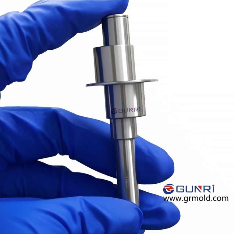
Ejector pins are a fundamental component in the manufacturing of parts, playing a pivotal role in the ejection system of molds, ultimately influencing the final product quality in the injection molding process. Injection molding entails the injection of molten plastic into a metal mold to conform to the mold’s shape. Injection molding ejector pins are primarily responsible for removing the finished parts from the die molds. The metal mold is composed of two parts: the A-side and the B-side. As the molten material cools within the mold, both halves of the metal mold separate, enabling the extraction of the solidified plastic. When the mold is opened, the A-side is lifted, leaving the molded part on the B-side.
Ejector pins are positioned on the B-side of the mold and function to push the molded part out of the mold. An ejector pin’s presence is typically marked by a dimple imprinted on the finished products.
Types of Ejector Pins
Several types of ejector pins are used in product manufacturing. The following are the most common types suitable for various processes:
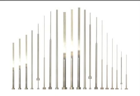
- Through-Hardened Ejector Pins: These ejector pins undergo heat treatment to ensure consistent hardness across the entire pin diameter. They can endure operating temperatures of up to 200°C and are ideal for plastic ejection systems within molds.
- Nitrided Ejector Pins: Also known as Nitrided H13 pins, these are considerably harder than through-hardened pins and are well-suited for die-casting ejection systems in molds. Nitrided pins are nitrided to 65 – 70 HRC and can withstand temperatures exceeding 200°C.
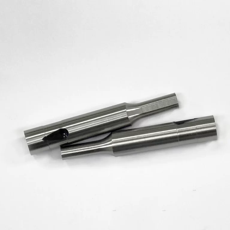
- Black Ejector Pins: Manufacturers developed these ejector pins in response to the limitation of Nitrided H13 pins, which cannot be used at working temperatures exceeding 600°C. The black ejector pin is coated with a black surface treatment, rendering it self-lubricating and capable of withstanding high temperatures of up to 1000°C. This type of ejector pin is more expensive and is suitable for use in metal ejection systems for automotive molds.
Key Considerations for the Top Ejector System
To optimize the performance of an ejector system, several important considerations must be taken into account:
- Maintain Adequate Hole Spacing: Ensure a minimum distance of at least 3/32 inches between the ejector pin hole and other holes to prevent interference.
- Provide Relief Clearances: Offer a 1/64-inch relief for ejector pin holes on the ejector plate and a 1/32-inch clearance for ejector pin holes on the template.
- Utilize Standardized Pin Sizes: Stick to standard-sized ejector pins and avoid grinding down their tips to ensure consistency.
- Material and Diameter Matching: When working with different materials, accurately measure the diameter of each ejector pin to avoid deviations greater than 0.02 millimeters between pins and holes.
- Ensure Vertical and Smooth Holes: All ejector pin holes must be perfectly vertical, and their surfaces should have a smooth finish (Ra~0.25μm) to guarantee smooth pin operation.
- Adjust Hole Diameter: Depending on the material used, adjust the hole diameter accordingly. For materials like PE/PP/Nylon, the hole diameter should match the pin diameter + 0.01 millimeters, whereas for HIPS/PC/ABS materials, it should match the pin size + 0.02 millimeters.
- Ensure Proper Assembly: Ejector pins should pass directly through the bottom plate, ejector plate, and mold. After installing all ejector pins, confirm that the ejector plate can move freely.
- Proper Labeling and Orientation: To prevent assembly errors, ensure that all ejector pins and ejector plate interface slots are clearly labeled with corresponding markings and face the same direction.
- Retention Slots: All molded ejector pins should have retention slots to avoid assembly errors.
- Thorough Inspection: Before covering with the backing plate, conduct a detailed inspection to identify misalignments or omissions after installing ejector pins.
- Parallel Ejection Design: In designing the ejector pin positions, consider both ejecting force and the ability to eject the finished product in a parallel manner.
- Ejector Pin Types: Ejector pins are primarily available in two types, full-hard and nitrided. Pay special attention to surface hardness and core hardness.
Optimizing the Ejector System for Enhanced Injection Molding Efficiency
In the realm of injection molding, the ejector system plays a pivotal role in ensuring the smooth ejection of finished products from molds, directly affecting production efficiency and product quality. To maximize system performance, it’s imperative to consider the following critical factors:
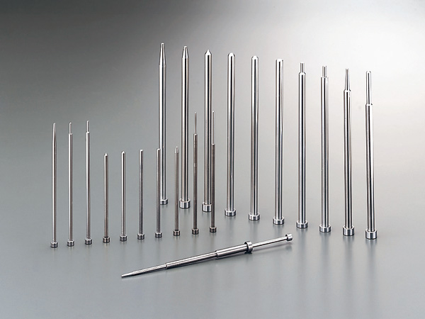
- Maintain Adequate Hole Spacing: Ensure a minimum distance of at least 3/32 inches between the ejector pin hole and other holes to prevent interference and conflicts.
- Provide Relief Clearances: Offer a 1/64-inch relief for ejector pin holes on the ejector plate and a 1/32-inch clearance for ejector pin holes on the template. These clearances are vital for the proper operation of ejector pins.
- Standardized Pin Sizes: Stick to standard-sized ejector pins and avoid altering their tips. This approach ensures uniformity and consistent performance.
- Material and Diameter Matching: When working with different materials, such as injection-molded nylon and thermoplastics, it’s essential to measure the diameter of each ejector pin accurately. Deviations exceeding 0.02 millimeters between pins and holes can lead to batch issues.
- Vertical and Smooth Holes: All ejector pin holes must be perfectly vertical, with a smooth finish (Ra~0.25μm) on their surfaces. This smoothness is vital to the seamless operation of the ejector pins.
- Hole Diameter Adjustment: Depending on the material used, adjust the hole diameter accordingly. For materials like PE/PP/Nylon, match the hole diameter with the pin diameter + 0.01 millimeters. For HIPS/PC/ABS materials, ensure the hole diameter corresponds to the pin size + 0.02 millimeters.
- Thorough Assembly: Ejector pins should pass straight through the bottom plate, ejector plate, and mold. After installing all ejector pins, ensure that the ejector plate can move freely.
- Proper Labeling and Orientation: To avoid assembly errors,all ejector pins and interface slots on the ejector plate should be clearly labeled with corresponding markings, and they should face the same direction.Retention Slots: It’s important to incorporate retention slots in all molded ejector pins to prevent assembly errors.
- Comprehensive Inspection: After installing the ejector pins, conduct a thorough inspection to identify any misalignments or omissions before covering them with the backing plate.
- Parallel Ejection Design: When positioning ejector pins, consider not only the force required for ejection but also the need for the finished product to be ejected in a parallel manner.
- Ejector Pin Types: Ejector pins are typically categorized as either full-hard or nitrided. Pay special attention to both surface hardness and core hardness.


