Guide Pillar Clearance & Fit: A Step-by-Step Guide to Precision Engineering
Why This Matters
In mold design, a 0.1mm error in guide pillar clearance can reduce die lifespan by 30%. Improper guide pillar fit may cause misalignment, costing manufacturers $50k+ annually in downtime. This guide demystifies tolerance calculations with real-world examples and actionable formulas.
1. Understanding Guide Pillar Clearance & Fit
What is Clearance Fit?
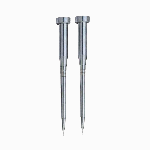
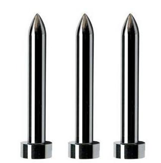
Clearance fit ensures the guide sleeve (hole) is intentionally larger than the guide pillar (shaft). The resulting gap allows smooth linear motion while avoiding friction damage.
Key Rules
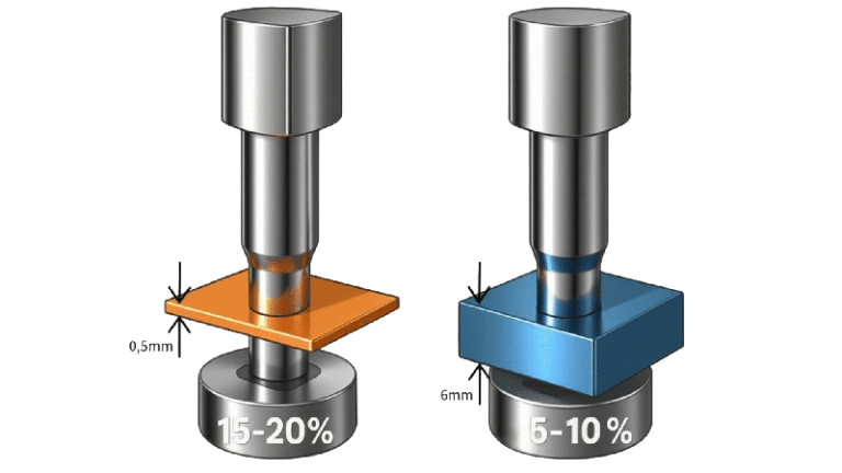
- Minimum Clearance: Must exceed functional requirements (e.g., 0.08mm for injection molds).
- Maximum Clearance: Must limit to prevent play (e.g., <0.13mm for high-precision systems).
Pro Tip: Use “8分” = 0.08mm (1分 = 0.01mm) in metric systems.
2. Calculation Workflow
Step 1: Define Basic Dimensions
- Example: Guide pillar/sleeve nominal diameter = 16mm.
Step 2: Calculate Clearance Range
Minimum ClearanceMaximum Clearance=Sleeve Lower Limit−Pillar Upper Limit=Sleeve Upper Limit−Pillar Lower Limit
3. Case Study: Solving a Tolerance Conflict
Original Design Failure
| Component | Tolerance | Actual Clearance |
|---|---|---|
| Guide Pillar | Φ16₋₀.₀₁₈⁻₀.₀₄₀ | 0.020mm (too small) |
| Guide Sleeve | Φ16⁺₀.₀₀₂⁺₀.₀₂₅ | → Function failure |
Root Cause: Minimum clearance (0.02mm) caused binding during high-speed operation.
Revised Design Using Tolerance Logic
Step 1: Set Minimum Clearance Requirement
Target: 0.08mm (customer specification).
Step 2: Solve for Sleeve Tolerance
Sleeve Lower Limit≥Pillar Upper Limit+0.08mmSleeve Lower Limit≥15.980+0.08=16.060mm
Step 3: Define Final Tolerance
| Component | Revised Tolerance | Clearance Range |
|---|---|---|
| Guide Pillar | Φ16₋₀.₀₂₀⁻₀.₀₅₀ | 0.08mm~0.13mm |
| Guide Sleeve | Φ16⁺₀.₀₆₀⁺₀.₀₈₀ | (15.950–15.980 vs 16.060–16.080) |
Validation:
- Minimum Clearance: 16.060 – 15.980 = 0.08mm ✅
- Maximum Clearance: 16.080 – 15.950 = 0.13mm ⚠️ Test under load conditions
4. Critical Decision Checklist
- Unit Clarity: Confirm “分” to mm conversion (1分=0.01mm).
- Manufacturing Feasibility: Avoid over-tight tolerances (e.g., ±0.005mm increases cost 200%).
- Application-Specific Testing: Validate with real-world loads and speeds.
5. Why This Approach Wins
- Cost-Efficient: Balances precision and machining costs.
- Risk-Reduction: Predefined clearance ranges prevent assembly failures.
- Scalable: Apply the same logic to other components (e.g., linear rails).
Actionable Takeaway
“When specifying guide pillar fit, always tie minimum clearance to functional requirements (e.g., ‘0.08mm for 500kg injection force’), not arbitrary numbers.”
Struggling with guide pillar misalignment? Share your tolerance challenges in the comments—we’ll provide free troubleshooting!