Custom Mold Bases
Currently, molds are used in the production of every type of product, including automobiles, aerospace, consumer goods, electrical and communication devices, medical equipment, and more.
Whenever there is a need for high-volume production, molds are employed, and the mold base is an integral part of the mold. Precision requirements for mold bases vary at different levels based on the specific product requirements.
GUNRI mold bases are precisely tailored to meet the diverse needs of various customers, providing suitable solutions.
Description
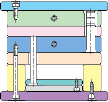
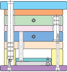
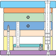
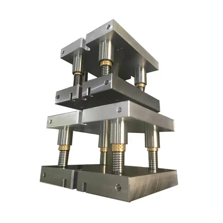
In simple terms, the mold base consists of a preforming device, positioning device, and ejector device. It is generally configured with panels, A plate (front template), B plate (rear template), C plate (guide rail), bottom plate, top pin plate, top pin base plate, as well as accessories like guide pillars and return pins.
The diagram above illustrates a typical mold base structure. The right side is referred to as the upper mold, and the left side is called the lower mold. During injection molding, the upper and lower molds first come together to shape the plastic in the mold components. Subsequently, the upper and lower molds separate, and the finished product is ejected primarily by the ejector device in the lower mold.
Upper Mold (Front Mold) Configured for the inner mold component forming section or the core component forming section. Runner system (including hot nozzles, hot runners (pneumatic section), and conventional runners). Cooling system (water channels).
Lower Mold (Rear Mold) Configured for the inner mold component forming section or the core component forming section. Ejection devices (product push plates, ejector pins, stripper rings, angle pins, etc.). Cooling system (water channels). Fixing devices (support heads, guide rails, and pin plate guides, etc.).
This description outlines the components and functions of a mold base in the context of injection molding. The upper and lower molds collaborate to shape the plastic material, and the ejection of the finished product is primarily facilitated by the ejector devices in the lower mold.


