Ultimate Guide to Stamping Die Components: Key Elements & Functions
Introduction to Stamping Die Components
Stamping dies are complex systems that shape metal sheets into precise parts. Understanding their core components—die plates, guide pins, punches, springs, and more—is critical for optimizing performance, reducing downtime, and improving product quality. This guide breaks down each key element, its role, and industry best practices.
Core Stamping Die Components Explained
(Primary Keyword: “stamping die components”)
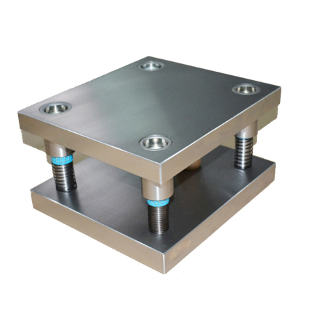
1. Die Plates (Foundation)
- Function: Base structure for mounting all components
- Key Features:
- Material: High-strength steel (AISI 4140 or S50C)
- Precision: Flatness ≤0.02mm/m² for alignment
- Types: Upper/lower plates with standardized bolt patterns
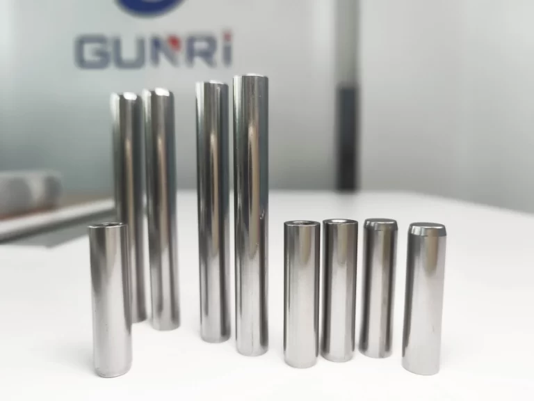
2. Guide Pins & Bushings (Alignment System)
- Purpose: Ensure ±0.003mm alignment between upper/lower dies
- Types:
- Friction Pins: Cost-effective for low-speed operations (<300 SPM)
- Ball Bearing Pins: High-speed compatible (up to 1,200 SPM)
- Surface Treatment: Hard chrome plating (HRC 60+) for wear resistance
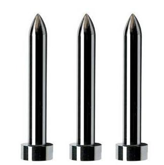
3. Punches & Die Buttons (Cutting/Forming Tools)
- Punch Types:
- Blanking punches (shearing)
- Forming punches (bending/embossing)
- Material: Carbide inserts (YG15) with TD coating (HV2500)
- Clearance: 5-8% of material thickness for clean cuts
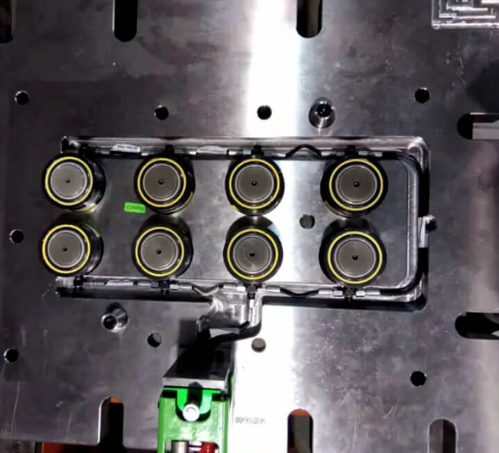
4. Die Springs (Pressure Control)
- Role: Maintain consistent stripping force
- Selection Guide:Spring TypeForce RangeLifespanColor CodeLight Duty50-500N500K cyclesYellowHeavy Duty1,000-5,000N1M+ cyclesBrown
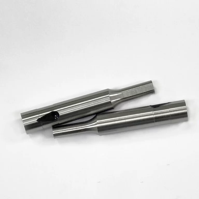
5. Retainers (Component Holders)
- Function: Secure punches/die buttons
- Locking Mechanisms:
- Ball-lock systems (fast tool changes)
- Shoulder-mounted designs (high stability)
6. Stripper Plates (Material Control)
- Operation:
- Pre-press material during cutting
- Eject finished parts smoothly
- Surface Finish: Micro-dimpled texture (Ra 0.8μm) prevents adhesion
Critical Design Considerations
(LSI Keywords: die component alignment, stamping tool maintenance)
- Tolerance Matching:
- Guide pin-to-bushing clearance: ≤0.005mm
- Punch/die button concentricity: ±0.01mm
- Material Selection Matrix:
| Component | Recommended Material | Hardness | Application |
|---|---|---|---|
| Punch Tips | Tungsten Carbide | HV 1,500 | High-volume runs |
| Die Buttons | D2 Tool Steel | HRC 58-62 | Complex geometries |
| Guide Bushings | Bronze Alloy | HB 80-100 | Self-lubricating |
- Lubrication Systems:
- Centralized oil circuits for high-speed dies
- Dry film lubricants for cleanroom environments
Industry Applications & Case Studies
(LSI Keywords: automotive stamping dies, precision die components)
- Automotive: Hood panel dies require 12+ component types for deep drawing
- Electronics: Connector stamping uses micro-punches (<0.5mm diameter)
- Case Study: Implementing ball-bearing guide pins reduced alignment errors by 40% in a HVAC component line.
FAQs About Stamping Die Components
Q: How often should die components be inspected?
A: Perform visual checks every 5,000 strokes and precision measurements every 25,000 strokes.
Q: What causes premature punch wear?
A: Improper clearance (>10% material thickness) or incorrect coating (e.g., using TiN instead of AlCrN).
Q: Can old die plates be reused?
A: Yes, after resurfacing (grinding tolerance: ±0.01mm) and hardness verification (HRC 40+).

