Assembly Steps for Mold Components
The Professional Guide to Precision Mold Component Assembly
In the world of high-precision injection molding, the assembly phase is where engineering design meets physical reality. A single micron of misalignment can lead to catastrophic tool failure, flash issues, or shortened cycle lives. This guide outlines the industry-standard assembly workflow for complex mold components, ensuring long-term tool reliability and part consistency.
I. Pre-Assembly Inspection & Cleanliness
Before a single bolt is tightened, the environment and components must meet strict cleanliness standards. In precision tooling, “clean” is a technical requirement, not a suggestion.
- Ultrasonic Cleaning: All inserts, pins, and cores should undergo ultrasonic cleaning to remove residual machining oils and micro-shavings.
- Deburring Check: Inspect all edges under magnification. Even a microscopic burr on a parting line can prevent the mold from seating properly.
- Material Verification: Cross-reference component hardness (HRC) and material grades against the design BOM (Bill of Materials) to ensure high-wear areas are correctly outfitted.
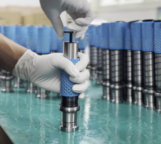
II. Sequential Assembly Workflow
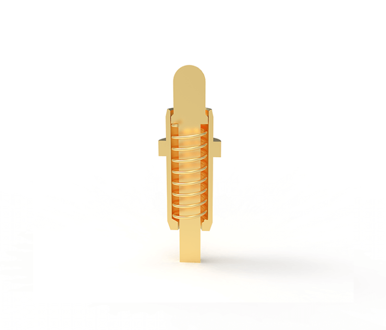
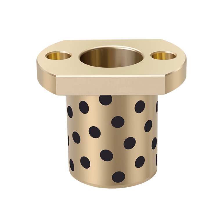
1. Guide System Installation (Pins & Bushings)
The foundation of mold alignment lies in the guide system. We utilize a slip-fit or light interference fit depending on the mold base requirements.
Pro-Tip: Always apply a high-quality molybdenum disulfide lubricant to prevent galling during the initial press-fit.
2. Core and Cavity Insert Integration
When seating inserts into the pocket, precision is paramount. We utilize Blueing (Prussian Blue) to verify the contact area between the insert and the pocket floor. A minimum 80% contact ratio is required to ensure uniform heat transfer and prevent “breathing” under high injection pressures.
3. Ejection System Synchronization
The ejector plate must move with zero friction. We check the clearance between ejector pins and their respective holes (typically maintained at 0.01mm to 0.02mm per side). After assembly, the system must be manually toggled to ensure a smooth “gravity drop” return.
4. Cooling Circuit Pressure Testing
Leaking water is the enemy of high-quality molding. Once the cooling circuits are assembled with Viton or Nitrile O-rings, we perform a static pressure test at 80-100 PSI for 20 minutes to guarantee seal integrity before the mold leaves the bench.
III. Technical Specification Table
Standard assembly tolerances for high-precision components:
| Component Type | Fit Category | Tolerance Range (mm) | Primary Metric |
|---|---|---|---|
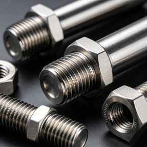
| Leader Pins / Bushings | Interference | +0.005 to +0.010 | Perpendicularity |
| Cavity Inserts | Transition | ±0.005 | Z-Axis Height Consistency |
| Ejector Pins | Clearance | +0.015 to +0.025 | Stroke Smoothness |
| Slide Wear Plates | Slip Fit | -0.010 to -0.020 | Thermal Expansion Gap |
⚠️ Expert Troubleshooting: Avoiding “Galling” and “Seizing”
One of the most common failures in newly assembled molds is component seizing during the first 100 cycles. To prevent this:
1. Differential Hardness: Ensure that sliding components (like lifters and wear plates) have a hardness difference of at least 2-5 HRC to prevent molecular bonding under friction.
2. Proper Torquing: Use a calibrated torque wrench for all socket head cap screws (SHCS). Uneven tightening of the mold base can cause the entire tool to “tweak,” leading to premature guide pillar wear.
Conclusion
Precision mold assembly is as much an art as it is a science. By following these rigorous steps and maintaining strict tolerance controls, you ensure that your tooling investment delivers millions of high-quality cycles. At GRMold, we specialize in high-tolerance components that make this assembly process seamless.
Need expert advice on your next tool build? Contact our engineering team today.
Need high-quality mold components for your production line? Browse our complete range of plastic mold components or contact our team for custom solutions and bulk pricing.