
Miniature Ball Bearing Guide Sets
GUNRI supplies miniature ball bearing guide sets comprising a guide shaft, a guide bushing and a ball cage fitted with steel balls. These components form a compact, cylindrical guide assembly for finite-stroke movement.
Selecting a miniature ball guide set requires more than choosing a shaft diameter. The mounting space, working stroke and loading conditions must be considered together with the dimensions of the bushing and cage.
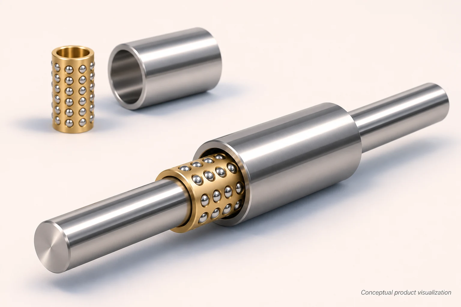
What Is Included in the Set?
| Component | Function in the assembly |
|---|---|
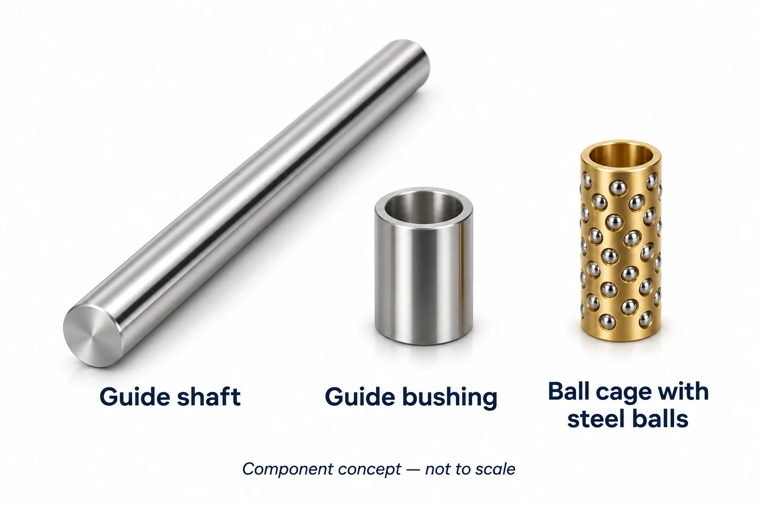
| Guide shaft / guide post | Provides the inner running surface for the balls and the connection to one part of the mechanism. |
| Guide bushing / guide bush | Provides the outer running surface and mounts in the surrounding structure. |
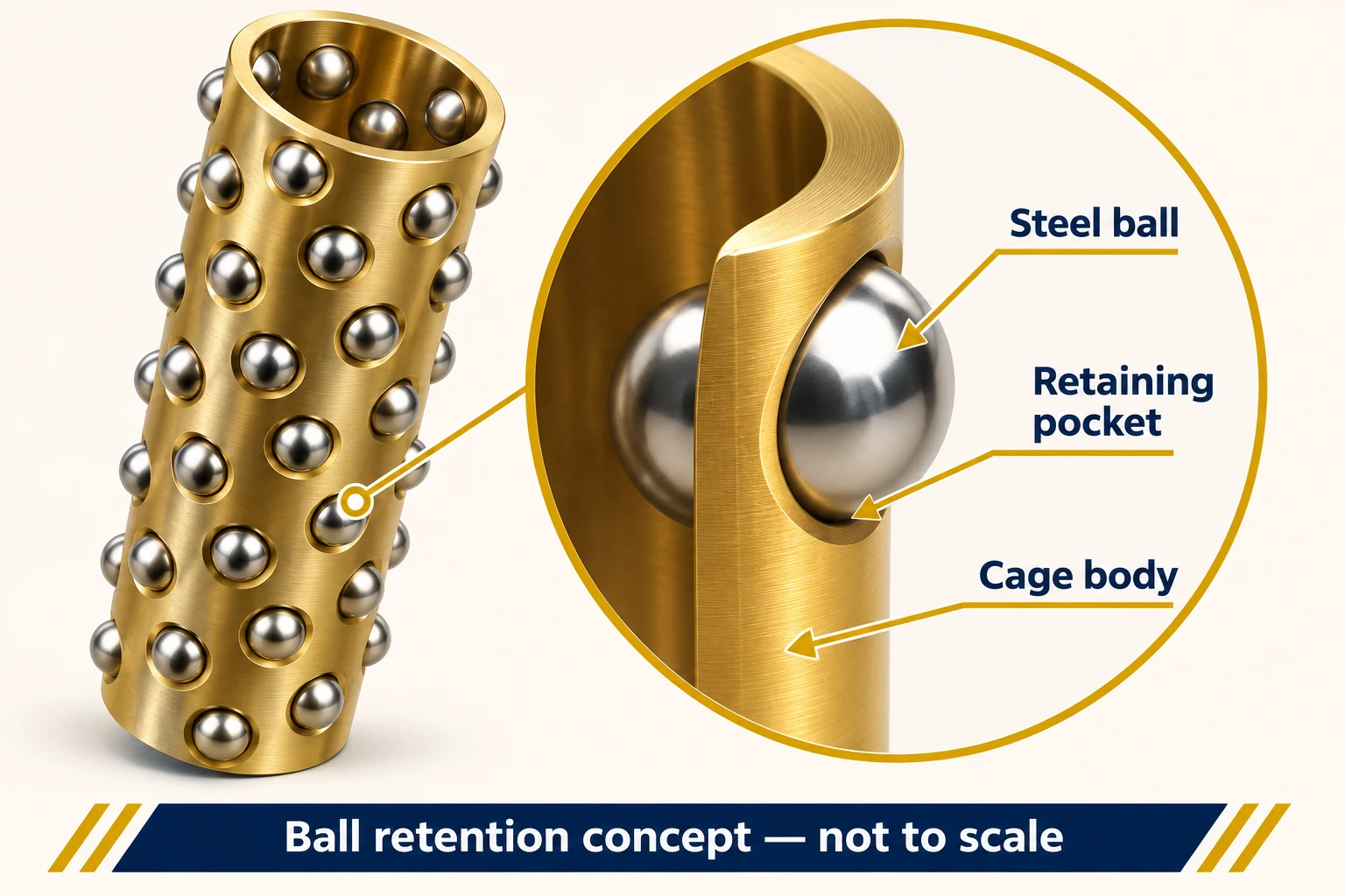
| Ball cage / ball retainer | Spaces and retains the balls between the shaft and bushing while allowing them to roll. |
| Steel balls | Contact the shaft and bushing to support rolling guidance. They are supplied within the cage. |
The complete set includes the shaft, bushing and ball-loaded cage. Confirm any retaining rings, stops, mounting hardware or other accessories separately when specifying the assembly.
Dimensions and Configuration
Use the following checklist to define the required assembly. Please include a dimensioned drawing where available.
| Specification | Information to provide |
|---|---|
| Shaft | Diameter, overall length, working surface and end details. |
| Bushing | Bore, outside diameter, length and mounting arrangement. |
| Ball cage | Length, ball diameter, ball arrangement and any retention features. |
| Working stroke | Required relative travel, end positions and available space for cage movement. |
| Fit and running condition | Required clearance or preload, mounting fits and acceptable running resistance. |
| Materials and finish | Requested material grades, hardness, surface requirements and corrosion considerations. |
Keep the dimension names separate
The shaft diameter is the diameter of the running shaft. The bushing bore is the diameter of the outer running surface. The cage body bore is a different feature from the circle defined by the inward-projecting ball surfaces. Mark each dimension on the drawing rather than using “ID” without identifying the component.
For a replacement, record the ball diameter and the lengths of both cage and bushing. A cage that fits over a shaft is not automatically a correctly paired bearing assembly.
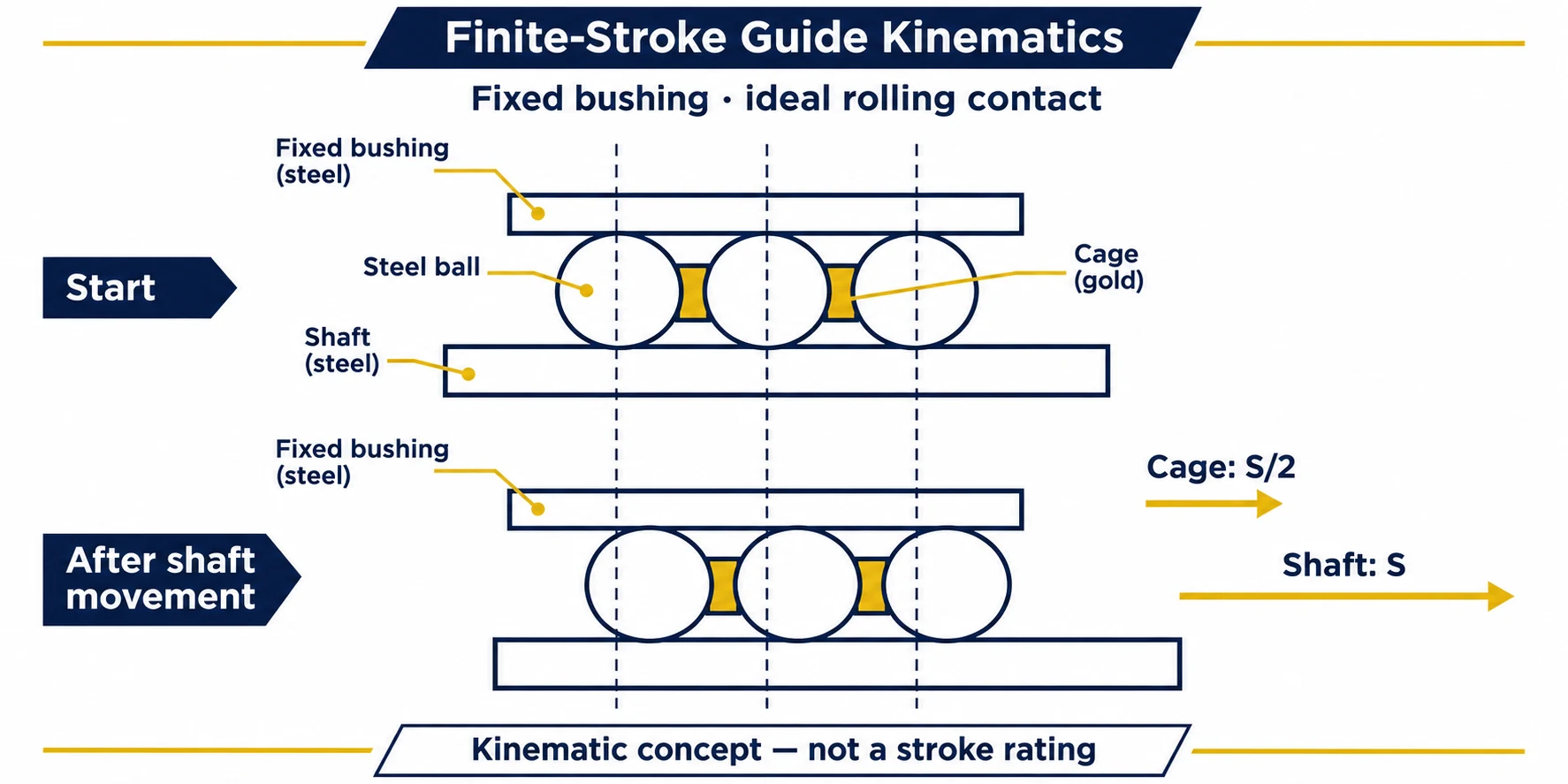
How the Guide Works
In this non-recirculating guide arrangement, the balls remain in the cage rather than passing through an endless return circuit. The cage moves along the running surfaces as the shaft and bushing move relative to each other.
With the bushing stationary and ideal rolling contact at both running surfaces, the cage moves in the same direction as the shaft by approximately half the shaft displacement. Available travel therefore depends on the relative positions of all three components.
Stroke and Contact Length
Check the assembly at both ends of its working stroke. The shaft and bushing must provide adequate contact with the ball-loaded cage throughout the intended movement. Cage length alone does not specify the usable stroke.
Stops and retention features must suit the assembly. Allowance may also be needed for cage migration during operation. Confirm the permitted travel and contact conditions on the approved assembly drawing.
Clearance, Mounting and Motion
Shaft diameter, ball diameter and bushing bore jointly affect clearance or preload. Mounting can change the bushing bore, so the installed condition matters when assessing the fit.
Some cylindrical ball-guide designs permit rotation or combined linear and rotary movement. If your mechanism requires either, state this in the inquiry so that the proposed GUNRI assembly can be assessed for that motion.
Which Guide Arrangement Does Your Mechanism Need?
| Arrangement | How guidance is provided | What to check first |
|---|---|---|
| Finite-stroke cylindrical ball guide | A ball-loaded cage moves between a round shaft and bushing. | Cage travel, contact at both end positions and the required rotational freedom. |
| Recirculating linear bushing | Balls pass between load-carrying and return paths. | Shaft support, travel, seals and model-specific operating limits. |
| Plain guide bushing | The shaft and bushing form a sliding contact pair. | Sliding material, lubrication, clearance and operating conditions. |
| Profile rail and carriage | A carriage travels along a profiled rail. | Rail mounting, load directions, moments and available installation space. |
These arrangements solve different guidance problems. Choose from the mechanism requirements; the presence of rolling elements alone does not establish load capacity, accuracy or service life.
Information Needed for Selection
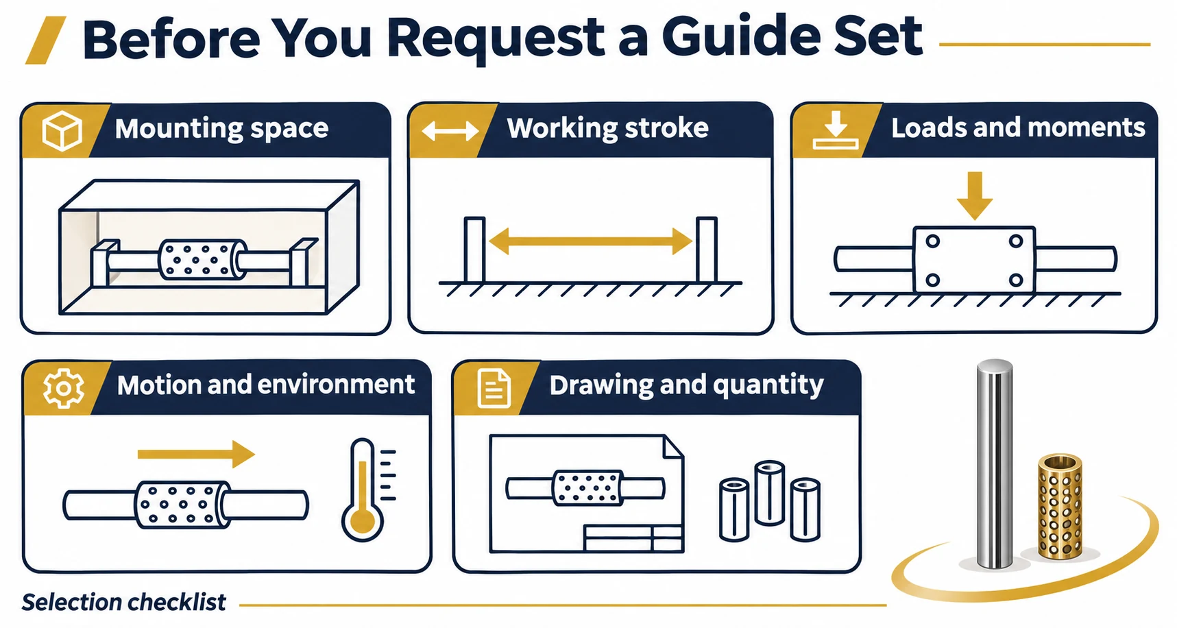
Please provide:
- A drawing of the assembly and its mounting space.
- Required stroke and the positions at each end of travel.
- Radial loads, moments and any shock or vibration.
- Motion type, speed, cycle frequency and mounting orientation.
- Operating temperature, contamination, corrosion and lubrication constraints.
- Required quantity and any inspection or documentation requirements.
For an existing assembly, include the original part number and available drawings. A similar external size is not sufficient to establish interchangeability: the ball size, running surfaces, fit and travel conditions also need to be checked.
Check three positions before placing an order
Identify which component is fixed, how the bushing is held and which shaft surface is available as the running track.
Show the shaft, cage and bushing together at one end position. Identify the stop and the region carrying the load.
Repeat the check at the other end. Confirm that the required working stroke does not rely on unsupported cage travel.
Replacement inquiry checklist
Send photographs of the separated components together with the original drawing or part number. Note the units, measured surfaces and condition of the sample. Identify wear or damage, because measurements taken from a worn running surface may not represent the original specification.
If rotation must be prevented, state this explicitly. A smooth round shaft assembly should not be assumed to provide the anti-rotation function of a splined shaft or a profiled rail.
Application Considerations
Manufacturer literature for this guide category identifies small measuring mechanisms and optical measuring spindles as potential uses. These are industry references, not GUNRI customer installations.
For your mechanism, assess the required movement and loading at the actual guide position. Application suitability must be checked against the selected assembly rather than inferred from the equipment category alone.
Frequently Asked Questions
Is this a complete guide set or a separate ball cage?
This page covers complete sets containing the guide shaft, guide bushing and ball-loaded cage. For cage components, see Brass Ball Cages.
Does a miniature ball bearing guide set provide unlimited linear travel?
The non-recirculating arrangement described here has a finite working stroke. Its usable travel must be established from the assembly geometry and contact conditions.
Can I select a set using the shaft diameter alone?
No. Include the bushing and cage dimensions, working stroke, mounting arrangement and loading conditions so the complete assembly can be assessed.
Can it be used for rotary movement?
State whether you need rotation alone or combined linear and rotary motion. The permitted motion and operating limits of the proposed GUNRI assembly require confirmation.
Does it require lubrication?
Confirm the lubricant and maintenance requirements for the selected assembly and operating environment. Do not assume that a ball guide is maintenance-free or suitable for dry running.
Can it replace another manufacturer’s guide set?
Provide the original model number and dimensional information for review. Compatibility requires checking the assembly fit and operating conditions; it cannot be established from a brand reference alone.
Discuss Your Guide Set Requirements
Send your drawing, required stroke, loading conditions and quantity with your inquiry. Identify any dimensions or operating requirements that are still open so they can be addressed during technical review.
Related Components
- Brass Ball Cages — separate cage components.
- Guide Bushes — related bushing products; verify the intended guide system before selecting.