Should Ejector Pins Be Tight? The Right Fit for Injection Molds
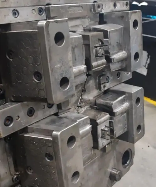
A few months ago, a mold shop called me in a panic. They were testing a new injection mold and every single ejector pin seized after the first five cycles. The mold had to be pulled, the core disassembled, and three pins came out bent. When I asked what fit they’d specified, the lead engineer said: “Zero clearance. We wanted them tight so the plastic wouldn’t flash.”
Sounds logical, right? Tight fit = no gaps = no flash. But in practice, that “logical” choice cost them two days of downtime and a $600 repair bill.
So should ejector pins be tight? And if not, how much clearance is actually correct?
No. Ejector pins should never be installed with an interference fit.
They require a controlled clearance — typically 0.005mm to 0.020mm — depending on diameter, material, and mold temperature.
International standards define three common fit classes for ejector pins: e7 (loosest), f6 (medium), and h7 (tightest). The choice depends on the pin diameter, the mold operating temperature, and whether the pin is mounted to the core or the ejector plate.
A practical rule of thumb: for pins under O6mm running at standard mold temperatures (80-100C), start with an f6 fit. For larger pins, high-temperature molds (120C+), or pins made from materials with high thermal expansion (like SKD61), step up to e7 to leave room for expansion. Need to know what diameters are available? Check our ejector pin size guide.
Why “tight” destroys your mold
Thermal expansion is the #1 killer. A typical mold runs at 80-120C. The ejector pin heats up fast because it contacts the melt directly. At 100C, a O6mm steel pin expands by roughly 0.007mm. If your clearance is zero at room temp, that 0.007mm has nowhere to go — the pin seizes.
Galling is #2. Steel-on-steel contact under ejection pressure (50-100 MPa) creates micro-welds between pin and housing. Tight fit maximizes contact area, which maximizes galling.
The three standard fits at a glance
| Fit Class | Clearance (O3mm) | Clearance (O6mm) | Best Used For |
|---|---|---|---|
| e7 | 0.010 – 0.024mm | 0.013 – 0.030mm | High-temp molds, large pins, SKD61 |
| f6 | 0.006 – 0.017mm | 0.008 – 0.022mm | General injection molding |
| h7 | 0.000 – 0.010mm | 0.000 – 0.012mm | Low-temp molds, small precision pins |
How to measure fit on the shop floor
- Pin gauge + bore gauge — Measure pin dia with micrometer and housing bore with bore gauge. Subtract for clearance.
- Plug gauge — Tells you instantly if the bore is in tolerance.
- Gravity test — Hold core plate vertically, drop pin in. It should slide through under its own weight with a barely perceptible wobble.
What happens when you get it wrong
Too tight: Seizure within 50 cycles. Galling. Scored core holes needing re-sleeving.
Too loose: Pin wobbles during ejection. Flashing around pin head. Accelerated wear. Pin fracture from cyclic stress.
The sweet spot: Pin slides freely at operating temp with 0.005-0.015mm clearance. No binding, no flash.
FAQ
Q: Can PTFE bushings fix fit issues?
They reduce friction but shouldnt mask incorrect fit.
Q: Should I lubricate pins?
Yes – high-temp grease or dry film lube on the shank reduces startup friction.
Q: Does coating change the fit?
Yes. Coating adds 1-5 um per side. Add 0.005mm to bore for TiN-coated pins. Different pin materials also behave differently – see our comparison of SKD61 vs 65Mn ejector pins.
Q: What about flat pins?
Flat pins need slightly more clearance (0.010-0.025mm) due to non-circular thermal expansion.
Need help? Contact our engineering team.