How to Choose a Miniature Guide Set: Sizing, Stroke and Fit
To choose a miniature guide set, define the required motion and installation space first. Then check shaft and sleeve dimensions, usable stroke, radial and moment loads, running fit, mounting, and lubrication as a complete assembly. A matching shaft diameter alone is not enough.
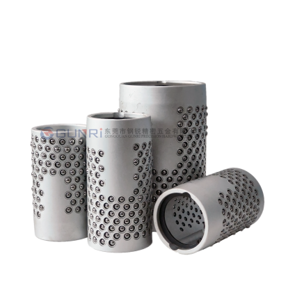
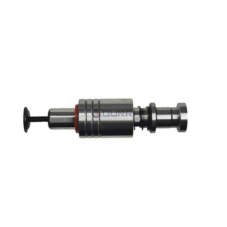
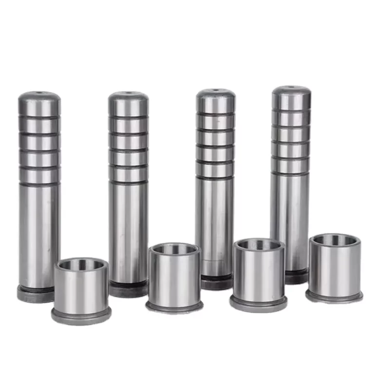
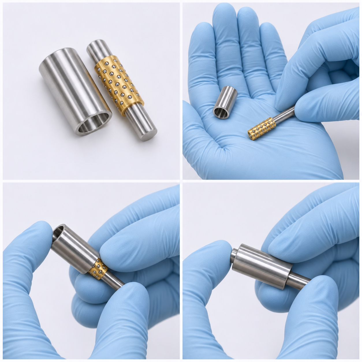
This guide covers cylindrical, finite-stroke miniature ball guide sets: a shaft, an outer sleeve or bushing, and a non-recirculating ball cage. It is intended for engineers specifying a compact mechanism and buyers preparing a technical enquiry. It does not cover miniature profiled-rail guides.
1. Confirm the motion before choosing a size
A miniature ball guide set supports a moving shaft or sleeve using retained rolling elements. Some cylindrical designs permit both axial travel and rotation; the permitted motion must be confirmed for the specific assembly. If your mechanism needs anti-rotation or torque transmission, do not assume a round ball guide provides it.
| Requirement | Selection implication |
|---|---|
| Short reciprocating axial movement | A finite-stroke ball guide may be a candidate; verify cage travel and engagement. |
| Axial movement plus rotation | Confirm that the selected assembly permits combined motion and meets the relevant load and speed conditions. |
| Long continuous linear travel | Compare a recirculating guide or another suitable arrangement; a finite cage has travel limits. |
| Controlled angular orientation or transmitted torque | Evaluate an anti-rotation feature, ball spline, or suitable rail guide rather than relying on a plain round assembly. |
Related catalog terminology includes “miniature ball bearing guide set” and “miniature stroke.” THK’s MST family, for example, combines a shaft, ball cage and nut. These names help locate relevant designs; they do not establish compatibility between manufacturers.
2. Define the installation envelope, not just shaft diameter
Sketch the mechanism in its closed and fully extended positions. Identify which component is fixed, which moves, and where external forces enter the assembly. Distinguish a sleeve’s running bore from its outside mounting diameter, and both from the cage body dimensions.
| Input | What to specify | Check before ordering |
|---|---|---|
| Shaft | Working diameter, overall length, end machining and mounting length | Does the working surface cover the required movement and engagement? |
| Sleeve | Maximum OD, overall length, shoulder and mounting method | Is there space for the shoulder, fastening tool and assembly access? |
| Cage | Length, ball arrangement and intended position | Can it travel without striking an end feature or leaving the intended running region? |
| Mechanism | Both end positions, moving mass and any separate stops | Are installation and service positions included? |
A thinner sleeve can help packaging, but a smaller outside diameter is not a free improvement. Check stiffness, manufacturing feasibility and the selected model’s load rating. Compare the actual series data rather than assigning every compact guide the same capacity.
3. Check usable stroke and cage travel together
In an ideal finite-stroke arrangement with a fixed outer sleeve and rolling contact without slip, the cage moves approximately half the shaft’s axial travel relative to the sleeve. Specify which part is fixed whenever discussing this relationship.
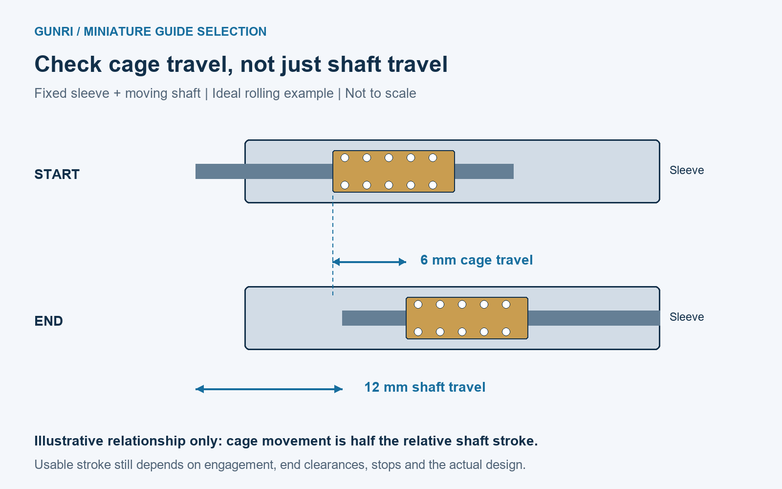
Worked example: a 12 mm reciprocating stroke
Assume the sleeve is fixed and the shaft must move 12 mm between its two operating positions. The nominal cage displacement is 6 mm. The next check is whether the cage can move those 6 mm while retaining the required ball engagement and end clearances at both positions.
This does not mean that a 6 mm cage is suitable, or that adding 6 mm to any sleeve length creates a valid design. Cage length, sleeve length, starting position, shaft support and retaining features must be checked together. A longer cage does not automatically increase available travel within a fixed sleeve.
Use the exact model drawing to establish the allowable stroke. The MISUMI catalog illustrates why cage displacement and shaft/bushing stroke must be treated separately. Its model-specific symbols and formulas should not be transferred to a different custom assembly without checking their definitions.
4. Specify loads and measurable performance
Identify radial forces, their application points, and any resulting moment about the guide. A small force acting at a long offset can create a significant moment. Do not assume the ball guide acts as an axial stop or a thrust bearing: define a separate load path for those functions unless the selected design explicitly provides them.
Provide speed, acceleration, cycle frequency, orientation and the expected number of cycles. Use supplier ratings and the relevant calculation method to assess capacity and life. A generic life equation is not useful when the model’s ratings or operating factors are unknown.
Replace “high precision” with a test requirement
- Radial play: where it is measured and under what test force.
- Running or breakaway force: speed, orientation, lubrication and test temperature.
- Repeatability: approach direction, load, stroke and number of repetitions.
- Runout or straightness: measurement datum, travel range and assembly condition.
These are different characteristics. A small stated clearance does not by itself guarantee the final machine’s positioning accuracy or repeatability.
5. Check running fit, mounting and environment
Separate rolling-contact clearance or preload from the fit used to mount the sleeve in its housing. The first depends on the working diameters, ball size and complete contact geometry. The second concerns how the sleeve is retained. Treating them as one “interference fit” can lead to an incorrect specification.
Agree tolerances and acceptance methods for the particular assembly. Do not apply a universal micrometer clearance range to every miniature guide set. A mounting fit or excessive clamping force may also affect a thin sleeve; the installed condition should be included in functional validation.
| Condition | Questions for design review |
|---|---|
| Corrosion or cleaning chemicals | Are all component materials, surface treatments and lubricant compatible? |
| Clean equipment or sensitive surfaces | What particle, residue and lubricant-migration limits apply? How will suitability be verified? |
| Temperature variation | Could differential expansion change the working fit or running force? |
| Dust, coolant or debris | What protection and maintenance provisions are available? |
| Restricted lubrication | What lubrication condition has actually been validated? Do not infer dry-running capability from cage material alone. |
Specify material requirements for the shaft, sleeve, balls and cage separately. A stainless shaft does not make every part corrosion-resistant, and a polymer cage does not make the whole assembly non-magnetic.
6. Approve the complete sample before repeat production
Confirm whether the purchase includes a complete matched set or only a replacement component. If parts from different suppliers are being mixed, review the actual dimensions, tolerances, retention and functional requirements. A similar model name or nominal diameter is not evidence of interchangeability.
- Drawing review: confirm interfaces, units, tolerances, material specifications and revision.
- Dimensional inspection: agree the characteristics, instruments and sampling plan before manufacture.
- Installed motion check: validate alignment, cage position, end clearance and force over the required stroke.
- Application test: assess the agreed performance at the intended loads, temperature, lubrication and duty cycle.
- Approval record: record results and deviations; define what changes require a new sample review.
Dimensional acceptance alone does not prove service life. Equally, smooth hand movement does not establish compliance with a numerical repeatability requirement.
Copy-ready miniature guide set enquiry checklist
Use the following list to prepare a selection or manufacturing review. Leave genuinely unknown requirements marked “to be confirmed.”
- Application and motion: axial / rotary / combined; fixed and moving parts.
- Required operating stroke and service/opening positions.
- Shaft diameter, total length, working length and end features.
- Available sleeve OD, length, shoulder and housing details.
- Radial forces, load offsets, moving mass and separate axial load path.
- Speed, acceleration, frequency, orientation and intended duty.
- Required running force, play, accuracy or repeatability, with test conditions.
- Environment, materials, lubricant restrictions and maintenance access.
- Complete set or separate components; reference model/drawing if applicable.
- Prototype quantity, subsequent quantity and inspection/approval requirements.
Need a guide set reviewed against your drawing?
Send GUNRI the available space, shaft dimensions, required stroke and load conditions, together with a drawing or sketch. We can review the information needed for a custom manufacturing quotation. Fit and performance requirements must be agreed for the actual assembly.
Send Your Guide Set Requirements
See the custom miniature ball bearing guide set overview for the related manufacturing enquiry.
Frequently asked questions
What is included in a miniature guide set?
For the cylindrical type discussed here, the core components are a shaft, sleeve or bushing, and a ball cage with retained balls. Check whether stops, mounting parts or other accessories are included in the quotation.
Can it move linearly and rotate?
Some cylindrical assemblies allow combined motion. Confirm the selected design’s permitted motion and operating limits. Do not assume it provides anti-rotation or torque transmission.
Is a smaller clearance always better?
No. The required clearance or preload must suit the load, friction, geometry and operating conditions. Specify the performance to be achieved and validate the assembled guide.
Can a standard set be replaced with a custom set?
A custom component can be evaluated against the required dimensions and function, but the replacement needs drawing and sample approval. Model-name similarity is not sufficient.