Ball Cages for Manual Optical Translation Stages
You are aligning a laser diode on an optical bench. You turn the micrometer barrel on a manual X-Y stage and the carriage sticks for half a turn, then jumps. That stick-slip comes from the dovetail sliding against itself under preload. You can feel it in your fingertips through the micrometer, and you cannot hold a position to a few micrometers when the motion is not smooth.
The fix most builders reach for is a set of cross-roller bearings or a miniature linear rail. Those work, but they are expensive and they demand a precision-machined raceway on both the fixed and moving members. A lower-cost, lower-profile option is a ball retainer — a thin strip or sleeve of balls running between the way surfaces. This is the same idea used in manual optical translation stages for decades, and it is still a reasonable engineering choice when the load is light and the travel is short.
How a Ball Retainer Sits in a Dovetail or V-Groove
In a dovetail stage, the moving carriage mates to a fixed base at an angle — usually 30 or 45 degrees. Under the preload spring or adjustment screw, the two angled faces press against each other. Without rolling elements, those faces slide and stick.
A ball retainer sits between the two way surfaces. Rows of balls run in the dovetail contact band, carrying the preload on rolling contact. The retainer itself is a thin strip — not a sleeve — with ball pockets punched or machined along its length. The balls are captured in the pockets so they cannot migrate sideways, and the retainer cycles back and forth at half the carriage travel so the balls do not run off the ends of the way.
In a V-groove or crossed-roller arrangement, the same idea applies: the retainer keeps the balls evenly spaced and prevents them from rubbing against each other. Ball spacing matters. If balls touch, they spin against each other, drag increases, and the surface pits. A slotted-window retainer keeps pitch constant across the full travel.
Why a Custom Cage Beats Stock Balls Loose in the Way
A common DIY approach is to drop loose balls into the V-groove and cap them. That works for a bench prototype, but it has two failure modes. The balls drift and cluster at one end when you leave the stage parked, and they fall out when you lift the carriage off.
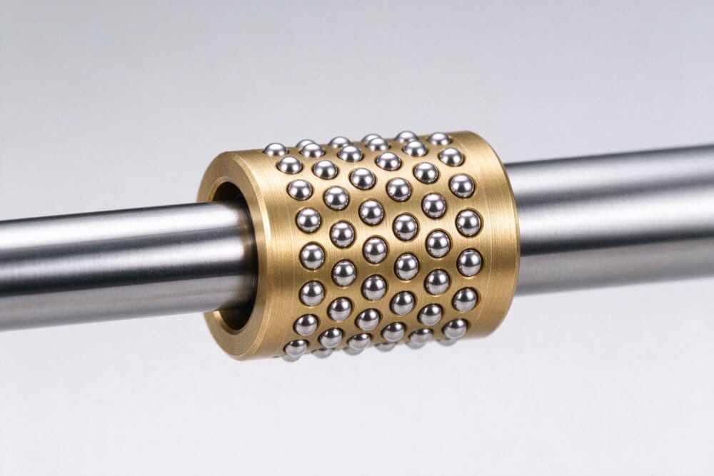
A custom ball cage solves both. The balls are staked — mechanically caulked into the cage windows — so they stay put through assembly, cleaning, and years of manual adjustment. The cage can be removed with the carriage and dropped back in without re-seating a handful of loose bearings. And because the cage is custom-machined, the ball pitch and row count match the way width exactly.
Geometry Choices That Matter on a Stage
Three geometry calls come up repeatedly on optical stage designs:
- Slotted windows instead of round holes. Elongated slots give the ball room to spin and reduce edge loading on the ball. We machine windows to your raceway width.
- Oil grooves along the cage faces. A light film of oil in the groove keeps the way surfaces lubricated over years of infrequent manual adjustment without pumping grease around a laser path.
- Multi-row arrangements when the stage carries an optics post or a sensor and needs moment stiffness. Two or three rows across the contact band spread the preload and resist yaw.
Material for a Bench-Stage Cage
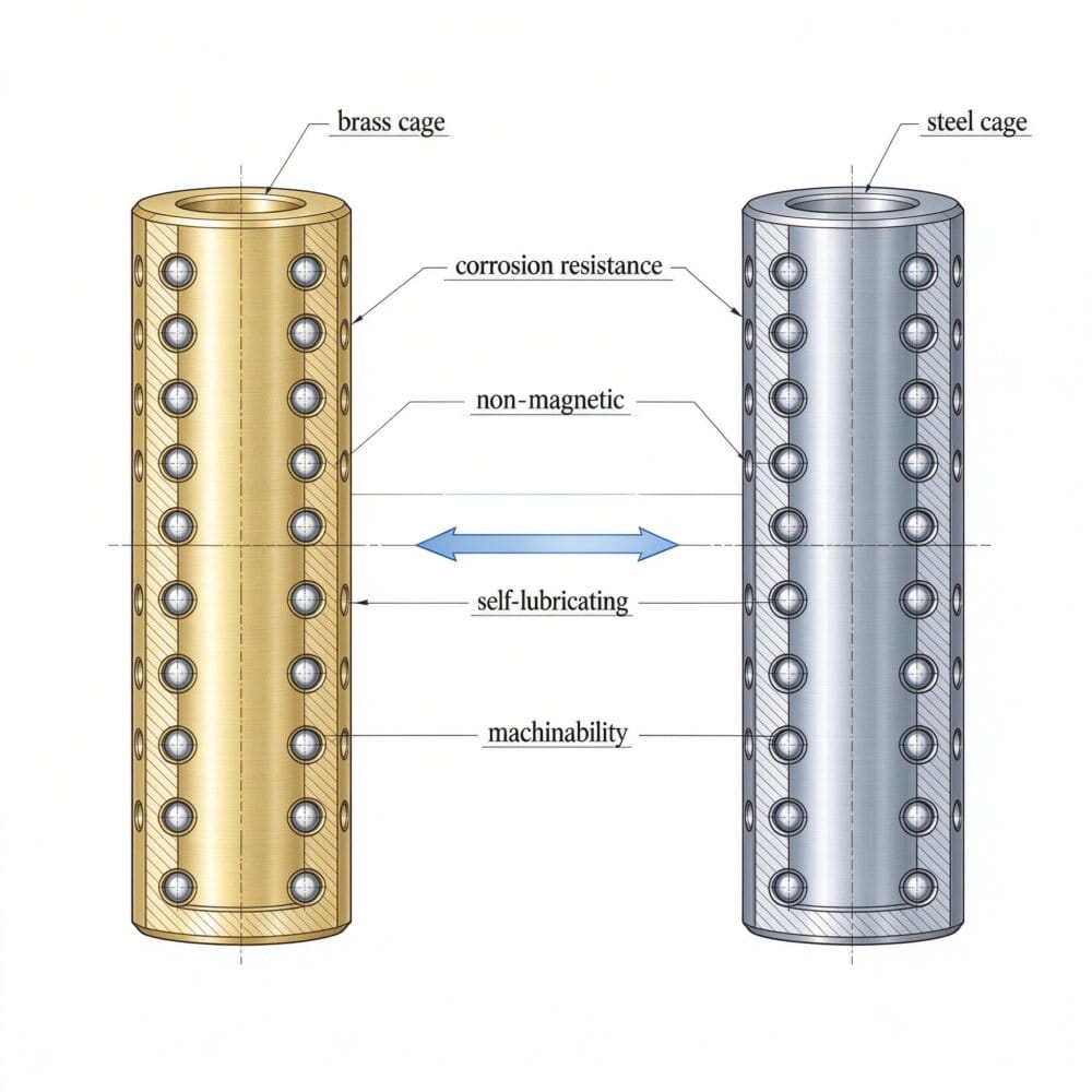
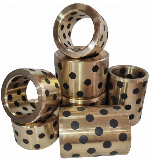
For a manual optical stage, the moving mass is small and the duty is light. Brass or bronze is the default cage material — easy to machine to tight window spacing, and it accepts optional graphite solid-lubricant plugs for dry running in clean-lab environments where oil is not wanted. Aluminum cuts weight on vertical stages. POM resin is a third option when the stage is disposable, cost-sensitive, or must run completely dry without any metal contamination on an optics bench.
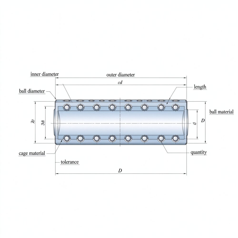
The ball size scales with the stage. Miniature stages with sub-millimeter way clearances use 0.6 mm balls. Larger lab stages with 50 mm travel use 1.5 to 3 mm balls. The cage itself can be as short as 8 mm and as small as 2.0 mm ID when the stage is built around a round shaft instead of a flat way.
When a Cage Is the Right Path
A ball retainer between dovetail surfaces is not the same as a recirculating linear rail. It is a finite-stroke, low-load guide. It is the right call when:
- The stage is manually adjusted, not motorized, and the user wants smooth, threshold-free motion through the micrometer.
- Loads are light — an optic, a camera, a fiber chuck — and the precision budget is about repeatability, not dynamic stiffness.
- The stage envelope is shallow and a linear rail block would stick above the way.
- You are replacing an obsolete retainer on an older stage and need a like-for-like part rather than a redesign.
The same rolling-retainer logic appears on microscope X-Y stages and on fiber-optic alignment assemblies, where manual micrometer adjustment and light loads are the norm. If you are choosing between a cage and a cartridge, the cage vs linear bearing comparison lays out the tradeoff in plain terms.
Replacing an Obsolete Retainer
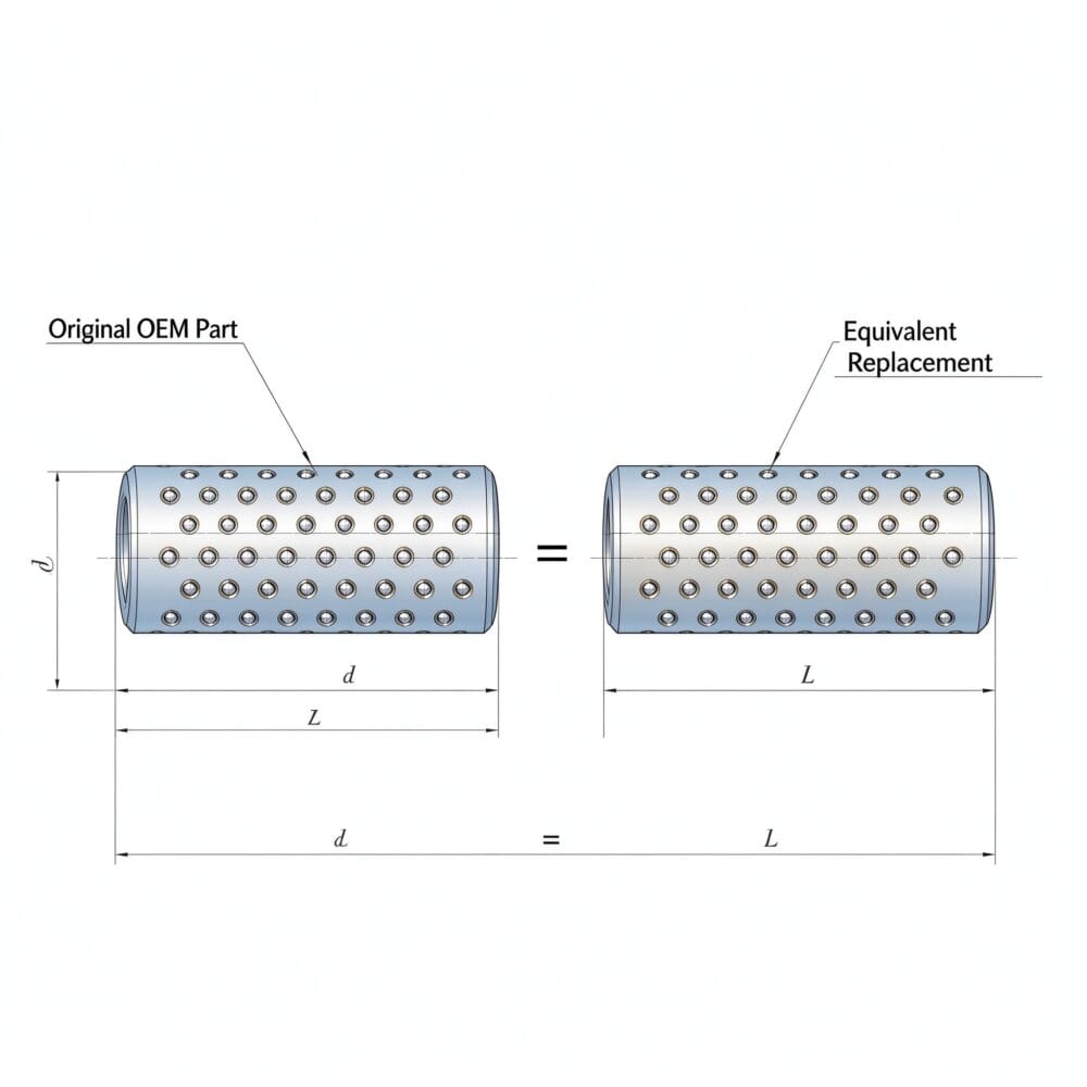
Aging optical stages from the 1980s and 1990s still show up on used equipment lists. The original ball retainer is lost, cracked, or the balls have rusted. We reverse-engineer these from a sample or a photo of the way profile and produce an interchange. We also supply equivalents to common off-the-shelf retainer lines when the drawing is available.
Send us the way width, the ball diameter currently in use, and the stroke. We work from your drawing or sample. Tolerances, preload, and material hardness are specified to your application. First articles are CMM-inspected, and there is no MOQ — a one-off replacement for a legacy stage is the same workflow as a 10,000-piece production run.
If you are replacing an Agathon, MISUMI, or FIBRO part, or designing a new mechanism, send us what you have.