
JIG & FIXTURE COMPONENTS
Drill Jig Bushings
Manufacturer
GUNRI manufactures drill jig bushings for drawing-defined jig and fixture requirements. Discuss standard-reference or custom drill bushes, from guide bore and mounting fit to quantity and production timing.
*Subject to quantity and complexity. Small orders carry a higher unit price. Confirm the schedule; shipping is separate.
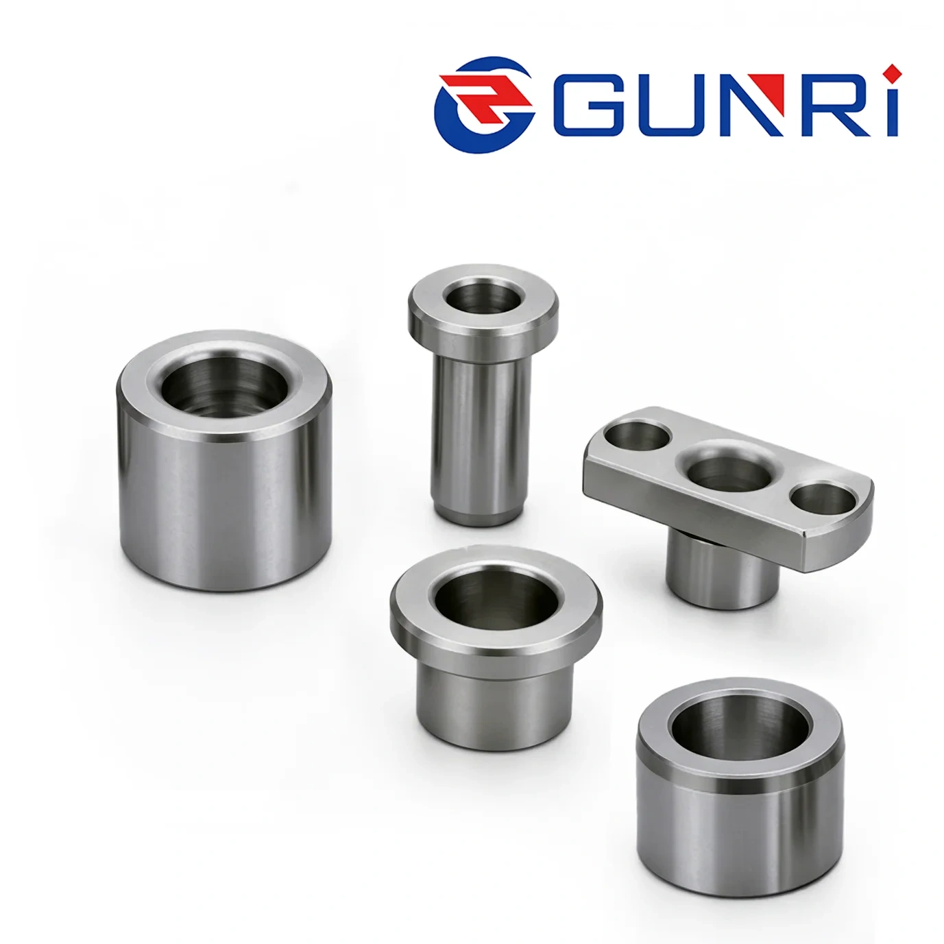
CHOOSE THE CONFIGURATION
Drill Jig Bushing Types
Compare five guide-bushing configurations by mounting method and replacement needs. Drill bushings are also called drill bushes or jig bushes. Match the full assembly drawing, not the bore size alone.
Configurations are available for drawing-based review. Final geometry, material, hardness, tolerances and supply suitability must be confirmed for your enquiry.
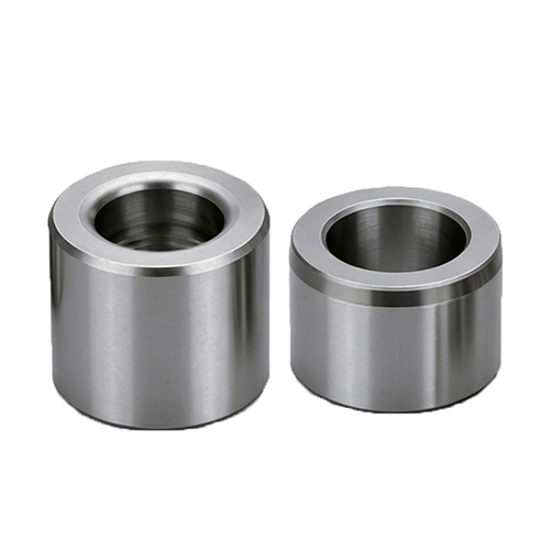
COMPACT DIRECT INSTALLATION
Headless press-fit
A headless guide bushing for direct installation in a jig plate. Specify the mounting fit, plate thickness and guide length.
Check: bore, body diameter, length and mounting fit.
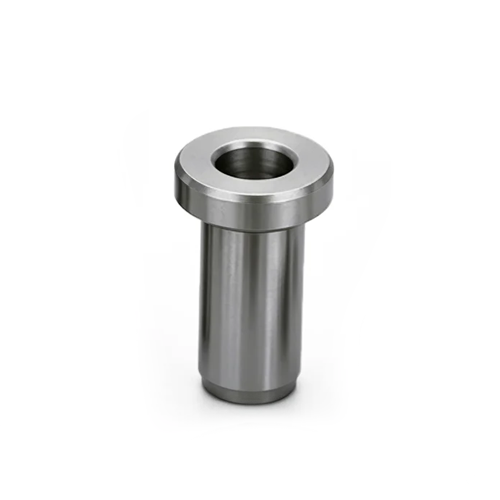
WITH A LOCATING SHOULDER
Headed press-fit
A press-fit configuration with a head that provides an axial locating surface. Allow space for the head and its seating face.
Check: body fit, head diameter, head thickness and seating detail.
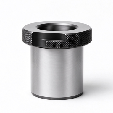
PLANNED GUIDE REPLACEMENT
Renewable bushing
A replaceable guide used with a compatible liner and retaining arrangement. Review the bushing, liner and locking detail together.
Check: mating liner, retaining detail and replacement access.
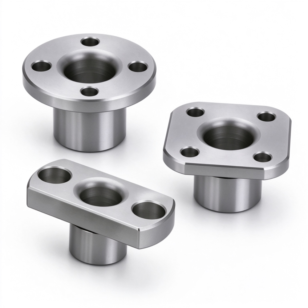
FLANGE-MOUNTED CONFIGURATIONS
Compact Flange Bushings
Configurable flange-mounted bushings for drawing-specific layouts. Confirm the required flange shape, seating face and mounting-hole pattern.
Check: flange outline, thickness, hole positions and mounting clearance.
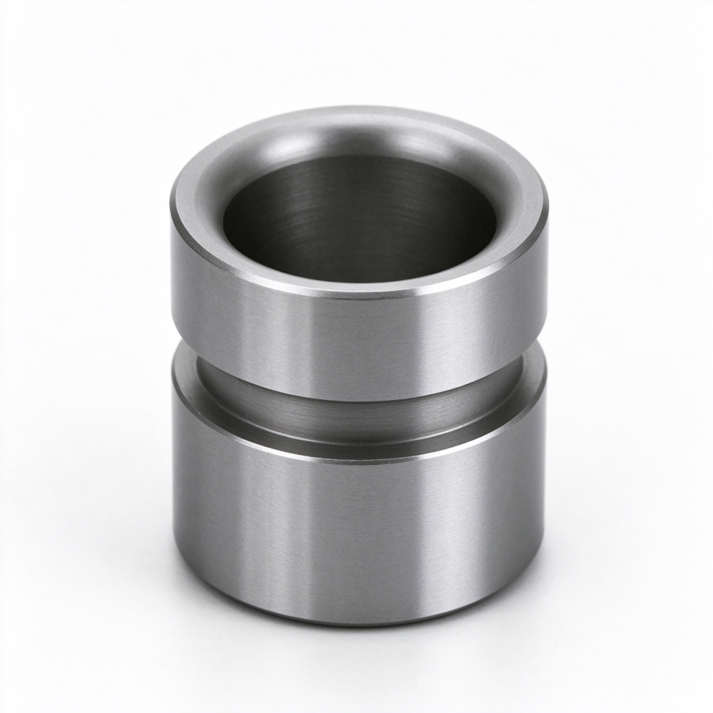
SET-SCREW RETAINING GROOVE
Grooved Straight Bushings
Configurable straight bushings with a set-screw retaining groove. Define the groove and mating screw arrangement on the assembly drawing.
Check: groove width, depth, axial position and retaining-screw location.
Liner bushings: supporting the renewable arrangement
A liner receives a compatible renewable bushing and helps protect the jig plate during replacement. Its bore fits the bushing, not the cutting tool. Include the liner and retaining details when requesting a renewable-bushing quotation.
Discuss your drawing, required quantity and mounting arrangement. Request a bushing quotation
CHOOSE THE ARRANGEMENT
How to Choose a Drill Jig Bushing
Start with the mounting and replacement arrangement, then define the guide bore and mating dimensions. The comparison below is a drawing-preparation guide, not a statement of interchangeable parts.
| Configuration | Mounting arrangement | Selection question | Drawing details to include |
|---|---|---|---|
| Headless press-fit | Jig plate mounting bore | Is a compact direct installation required? | Bore, outside diameter, length, plate thickness and mounting fit |
| Headed press-fit | Jig plate with head seating surface | Is there clearance for the head and its seat? | Body fit, head diameter, head thickness and seating detail |
| Renewable bushing | Compatible liner and retaining arrangement | Will the guide be replaced or changed between operations? | Mating liner dimensions, locking detail and replacement method |
| Compact flange bushing | Drawing-defined mounting bore and flange seat | Which flange shape and mounting-hole pattern fit the jig? | Flange outline and thickness, hole positions, mounting fit and clearance |
| Grooved straight bushing | Drawing-defined mounting bore with retaining screw | How will the screw engage and retain the bushing? | Groove width, depth and axial position, screw location and mating fit |
| Liner — supporting component | Jig plate | Which renewable bushing must it locate? | Mating bushing dimensions and agreed assembly fit |
Ordering a replacement?
Include the original drawing or part reference, mating dimensions and any wear or installation issue. Matching the bore or external appearance does not establish interchangeability.
SEE THE COMPONENT AT WORK
Drill Jig Bushing Applications
Drill bushings guide cutting tools in hole-making jigs. Related locating bushings receive pins to position pallets or fixtures. These examples show the difference, so you can specify the correct component for the job.
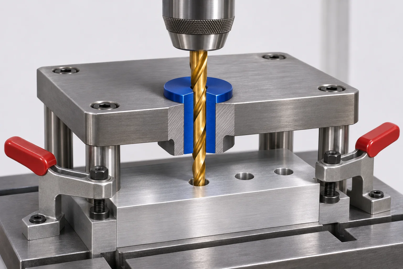
CUTTING-TOOL GUIDANCE
Guided drilling in a production jig
The jig plate holds a drill bushing above the clamped workpiece. Its guide bore directs the cutting tool before the tool enters the part.
- Locate and clamp the workpiece.
- Feed the drill through the guide bore into the workpiece.
- Retract the tool and unload the part; assess guide wear before replacement.
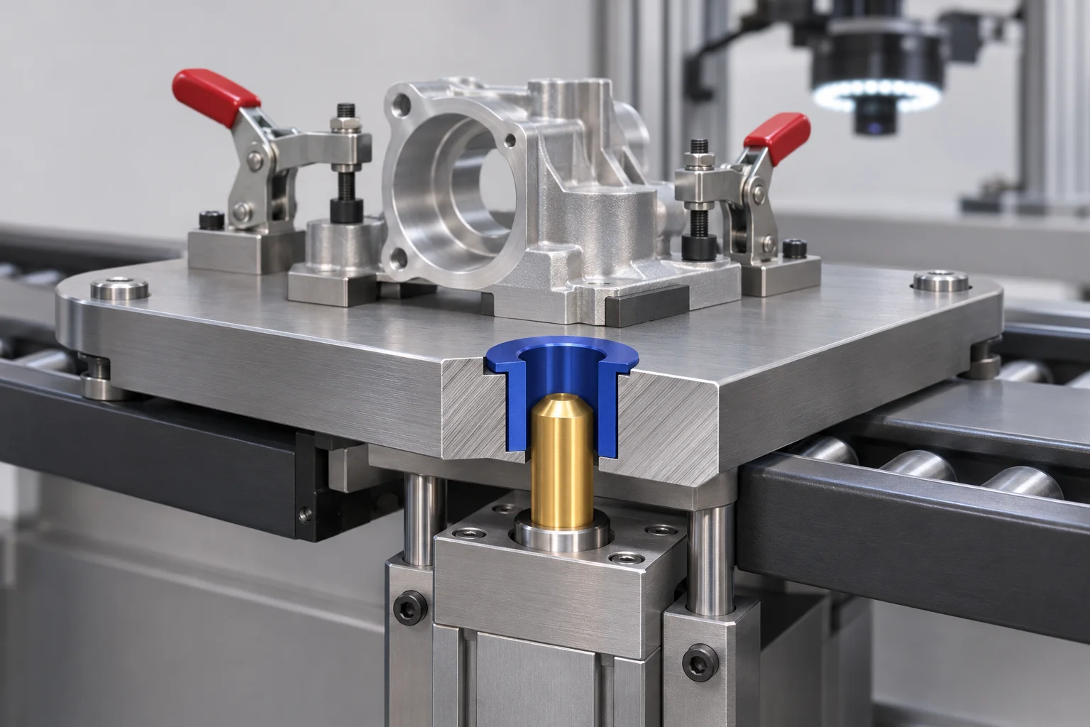
RELATED LOCATING-BUSHING APPLICATION
Pallet positioning at an inspection station
Here the bushing receives a locating pin, not a drill. The conveyor brings a carrier to the station; pin engagement establishes the pallet position for inspection or assembly.
- Stop the pallet at the workstation.
- Extend the locating pin into the pallet bushing.
- Withdraw the pin before releasing the pallet for transfer.
For drilling followed by reaming, discuss a renewable guide and compatible liner so each tool has the correct guide bore. For an existing jig, provide the original drawing and review worn mating surfaces before ordering a replacement.
FROM THE MECHANISM TO THE PRODUCTION CONTEXT
Industry & Process Contexts
Select by the fixture motion, mating part and operating environment as well as the industry.
LOCATING / FIXTURE TOOLING
Lithium-Battery Equipment
Module-assembly and inspection carriers can require pin-and-bush registration. Drilling jigs for fabricated brackets or tooling plates use drill-guide bushings instead. Specify which interface is required.
ASSEMBLY / CAMERA INSPECTION
Smartphone Manufacturing
Housing and carrier nests may need repeatable location during assembly, gauging or visual inspection. Identify the locating-pin interface separately from any tool-guiding bore used to machine fixture parts.
PRESS FITTING / CHECKING FIXTURES
Electronics & Electrical Assembly
Connector-assembly nests, light press-fitting fixtures and dimensional checks can use locating bushes. If the operation includes drilling or reaming, define the cutting-tool guide as a separate requirement.
HANDLING / INSPECTION TOOLING
Semiconductor Equipment Fixtures
Equipment handling and inspection fixtures may use pin-and-bush registration. Specify cleanliness, permissible wear debris and operating conditions when selecting the bushing for the equipment fixture.
ASSEMBLY / PART-MACHINING JIGS
Medical Equipment Tooling
Inspection nests, assembly fixtures and drilling jigs for equipment components have different bushing roles. Include the cleaning exposure, material and finished-condition requirements for the fixture.
CHANGEOVER / CARRIER REGISTRATION
Food & Packaging Machinery
Changeover tooling, carrier registration and machinery-part drilling jigs can require bushings. State the washdown, corrosion, lubrication and any food-contact requirements in the drawing enquiry.
Is the bore guiding a tool or receiving a pin?
Tool-guiding bore: include the cutting tool, guide length, jig-plate fit and chip-clearance arrangement.
Pin-locating bore: include the pin geometry, mating fit, motion, loading and environment.
DEFINE THE PART
Drill Bushing Dimensions & Specifications
Supply values from your drawing. Bore size alone does not define a drill jig bushing.
Schematic only. Head and retaining features require additional dimensions.
Specification checklist
- Geometry
- d, D, L; head or locking features where applicable
- Fit & precision
- Bore and OD limits, concentricity requirement, surface finish
- Material & treatment
- Required grade, hardness and treatment specification
- Application
- Tool, workpiece, operation sequence and replacement needs
- Order details
- Quantity, drawing revision, units and delivery destination
Non-standard requirements can be discussed against your drawing. There is no mandatory minimum order quantity; smaller orders generally carry a higher unit price. Production can generally be completed within 5 days, subject to quantity and part complexity. Confirm the schedule with your quotation; shipping time is separate. Materials, hardness, dimensional limits and standards remain subject to confirmation.
For flange-mounted designs, add the flange outline, thickness and mounting-hole pattern. For grooved straight designs, add groove width, depth, axial position and the mating screw location. For renewable designs, include the compatible liner and locking arrangement.
A CLEARER DRAWING ENQUIRY
Make the mating parts
part of the conversation.
Share the requirement
Drawing revision, units, quantity and the intended drilling or reaming operation.
Identify the interfaces
Jig plate, tool, liner and retaining details that affect installation and replacement.
Agree the order specification
Confirm dimensions, material, inspection requirements and commercial terms before ordering.
GUNRI MANUFACTURING
Why Discuss Your Drill Bushings with GUNRI?
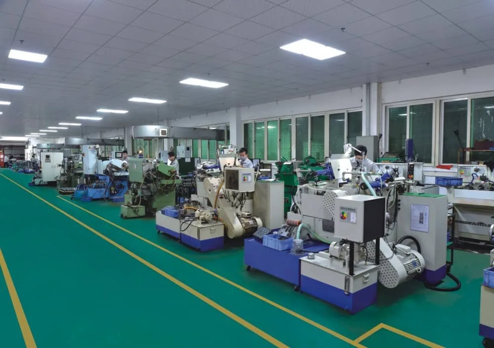
GUNRI is a precision component manufacturer. Its published factory information lists CNC turning, internal and cylindrical grinding, centerless grinding and honing equipment.
Drawing-based requirements
Discuss non-standard bore, body length, head or external geometry against a complete drawing. The quotation must establish feasibility and price for the specific part.
Flexible order quantities
There is no mandatory MOQ. Request the quantity you need; a smaller batch generally has a higher unit price.
Production timing
Production can generally be completed within 5 days, depending on quantity and complexity. Agree the actual schedule with the quotation; transit time is separate.
BEYOND A CATALOG REFERENCE
Custom Drill Bushings to Your Drawing
Provide the complete part geometry and the interfaces it must fit. Non-standard requirements can be discussed with GUNRI; dimensions and manufacturing feasibility are confirmed for each enquiry.
Define the geometry
Include bore, outside diameter, length, head or shoulder details, entry features and any retaining arrangement.
Define the finished condition
Specify material grade, heat treatment, hardness and the dimensional limits that apply after finishing.
Define acceptance
Identify critical characteristics, the drawing revision and the inspection records required with the order.
MATERIAL & QUALITY REVIEW
Material, Hardness & Inspection Requirements
Specify the finished component, not just a material name. Confirm the manufacturing and inspection requirements for your drawing before ordering.
Material & treatment
State the required grade, heat-treatment condition and hardness range. Specific GUNRI drill-bushing material options are awaiting confirmation.
Dimensions & surfaces
Identify bore and OD limits, length, surface finish and the required relationship between mating features. No universal numerical tolerance is stated for all configurations.
Inspection documentation
GUNRI’s factory page lists roundness, surface-roughness and hardness-testing resources. Confirm the measurements, sampling and records required for this order.
Factory-level equipment information does not establish the process route, achievable tolerance or inspection coverage of every drill bushing.
CONTINUE YOUR SELECTION
Drill Bushing Products & Ordering Guides
Use the existing product and engineering pages to discuss a configuration or prepare an enquiry. Confirm the applicable drawing and standard edition.
Headed drill bushings
Review the headed configuration and its mounting interfaces.
Headless drill bushings
Review the straight body, guide bore and installation dimensions.
Headed vs headless
Compare configurations before choosing the installation arrangement.
Drawing checklist
Collect geometry, mating parts and acceptance requirements.
BEFORE YOU ENQUIRE
Drill Jig Bushings: Manufacturing FAQ
Are drill bushes and drill bushings the same product category?
Both names are used for cutting-tool guides in drilling jigs. Match the drawing and specification rather than relying on the name alone.
How is a liner different from a drill bushing?
A guide bushing locates the cutting tool. A liner receives a compatible renewable bushing. The two bores serve different mating components.
Can I specify a metric or inch requirement?
State the units on your drawing and enquiry. Availability, size limits and the applicable specification must be confirmed; converting nominal dimensions does not establish an equivalent fit.
What if I only have a worn sample?
Provide photographs, a part reference if available, and information about the tool and mating components. A worn dimension may not represent the original design size. Confirm whether a sample-based assessment is available with GUNRI.
Is there a minimum order quantity?
There is no mandatory MOQ. Smaller quantities generally have a higher unit price. Include the required quantity for a quotation.
What is the typical production lead time?
Production can generally be completed within 5 days, depending on quantity and part complexity. Confirm the schedule before ordering. Shipping time is separate.
Can you assess a non-standard drawing?
Non-standard requirements can be discussed with GUNRI. Provide the drawing and quantity for feasibility, price and timing assessment.
Which materials, tolerances and standards are available?
Include your required grade, hardness, dimensional limits and standard revision in the enquiry. Suitability must be confirmed against the specific drawing; no blanket standards compliance or size range is stated here.
What should I specify for a compact flange bushing?
Send the required flange shape, seating dimensions, body fit and mounting-hole pattern with the guide bore and length. Check fastener access and surrounding clearance on the jig drawing. Final dimensions and supply suitability require confirmation.
What details are needed for a grooved straight bushing?
Include the external retaining groove width, depth and axial position, together with the mating set-screw location and mounting fit. A similar-looking groove does not establish compatibility with an existing assembly.
DRAWING-BASED ENQUIRY
Request a Drill Bushing Quotation
Send your drawing, quantity and specification requirements. GUNRI will review availability, price and production timing.
Your enquiry is saved for follow-up. Attachment formats and size limits are listed beside the upload field.
Thank you — your enquiry has been received.
Would you like to add WhatsApp as a backup contact? It can help us follow up if email does not reach you. This is optional — your enquiry is already saved, and you can skip this step.
GUNRI WhatsApp: +86 137 9020 1541