DIN 172 Headed Drill Bushings
A cylindrical guide body with an integral head for a defined seating interface in the jig plate. Manufactured to the specified DIN 172 reference and approved drawing.
- Bore, OD and length defined for your order
- Head and seating geometry reviewed with the fixture
- Material, hardness and inspection scope agreed before production
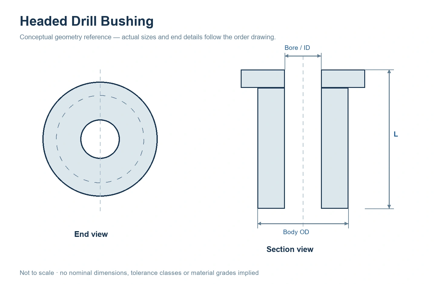
Gallery image: conceptual geometry reference, not to scale.
Description
Headed Press-Fit Drill Bushings
A cylindrical guide body with an integral head for a defined seating interface in the jig plate. GUNRI manufactures this product to customer-specified DIN 172 reference dimensions and approved drawings. Include the applicable edition, form, bore and mounting details so the quotation defines the part you need.
Head & Seating Geometry
Specify the head diameter, head thickness, seating face and available space around the head. If the fixture uses a recess, show the recess geometry and which surfaces establish location.
Guide Body & Bore
Define body OD, bore ID, overall length and effective guide length. Include the relationship between the bore, outside surface and seating face when these are controlled on your drawing.
The gallery drawing illustrates the general headed configuration. It is not a nominal-size table or a claim that every illustrated proportion is a DIN dimension.
Dimensions & Requirements to Specify
Use your controlled drawing or specified standard edition to define the component. The following checklist identifies the information we need; the quotation confirms the agreed dimensions and acceptance requirements.
| Item | Information needed |
|---|---|
| Reference | DIN 172 edition and form, or a customer-specific drawing; include units and revision. |
| Bore / ID | Nominal bore, tolerance, tool size and any entry or exit details. |
| Body OD | Outside diameter, tolerance and mating jig-plate bore. |
| Length | Overall length and effective guide length; show any internal relief or counterbore. |
| Head dimensions | Head OD, thickness, seating-face requirements and fixture recess if used. |
| Material & condition | Material grade, heat treatment, hardness method and final surface requirements. |
| Acceptance & supply | Critical geometric controls, inspection records, quantity and delivery destination. |
How to specify the DIN reference
DIN 172:1992-11 is marked withdrawn by DIN Media, while the designation remains a familiar purchasing reference. Include the edition and form stated by your drawing. A reference name alone does not define your material, final dimensions or inspection agreement. View the official standard record.
Manufacturing & Inspection
Our precision-component facility provides a basis for turning, grinding and honing work. The process route for your bushing is reviewed against its material, wall section, bore geometry and final condition.
Material & Treatment
Agree the grade, heat-treatment condition, hardness and surface requirements before manufacture. Identify the dimensions that apply after finishing.
Critical Geometry
Specify ID, OD and length checks plus drawing-defined relationships between the guiding bore and mounting surfaces. Measurement methods are matched to the part geometry.
Approval Records
State which characteristics require a report and whether sample or assembly approval is needed before repeat production.
View our equipment and quality-system information or explore precision component machining.
Check the Head, Plate and Tool Together
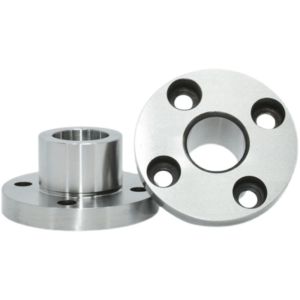
The head adds a seating feature, but the body and mounting hole still need their specified fit and geometry. Show the supporting surface, plate thickness and nearby components so the head does not create an unintended interference.
Provide the guided tool, effective guiding length and required access to the workpiece. Chip clearance and tool access are application requirements; they should be checked in the fixture design rather than inferred from the bushing photograph.
DIN 172 Headed Drill Bushings FAQ
Can GUNRI manufacture a DIN 172 reference part?
Yes. Send the required standard edition and form, dimensions, material, tolerances and quantity. We review the specification and manufacturing requirements before quotation.
Can the bore, length or external geometry be customized?
Drawing-based dimensions and special features can be reviewed for manufacture. Show the complete geometry and mating parts so the quotation identifies the agreed configuration.
What hardness and bore tolerance are available?
Specify the required values, material and finished condition on the drawing. They are reviewed for the particular size and geometry rather than assigned one value for every bushing.
What if I only have a sample or supplier part number?
Include that reference with the measured envelope, quantity and the interfaces that must be preserved. Dimensional and acceptance requirements need to be confirmed before manufacture.
Request a DIN 172 Headed Drill Bushings Quote
Send the drawing revision, standard reference, material, key dimensions and quantity. Include mating-part information and the checks required for approval.
- Units and standard edition
- Bore, OD and length
- Material, condition and tolerances
- Quantity and delivery requirements