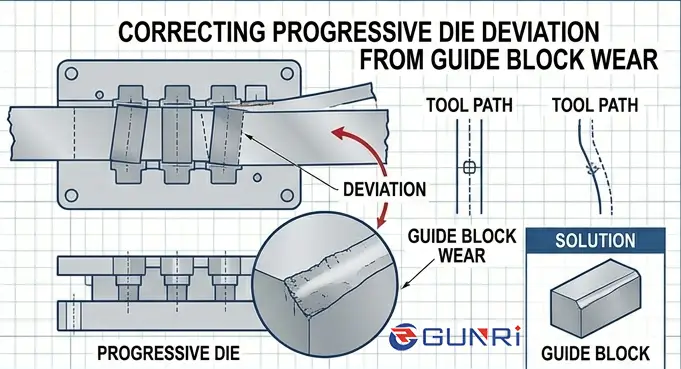
How to Correct Directional Deviation in Progressive Dies Caused by Guide Block Wear
I once watched a press operator spend six hours adjusting pilots and feeder timing on a progressive die that was producing parts 0.15 mm out of location at Station 8. Nothing he tried made any difference, because the root cause was not in the feed system. The die had 0.12 mm of wear on the guide blocks at Station 5 — a cutting station with unbalanced side thrust. By the time someone pulled the die and measured the guide block clearance with a feeler gauge, over $12,000 in labor and scrap had been wasted.
Why Guide Block Wear Causes Directional Deviation in Progressive Dies
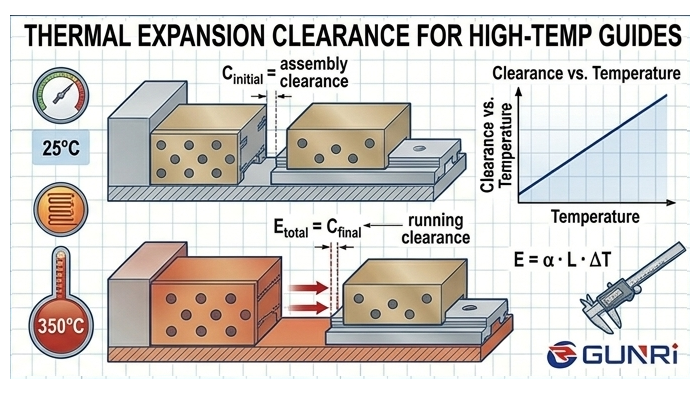
Guide blocks maintain the alignment between the upper and lower die shoes as the press cycles. When a guide block wears, the clearance between the block and its mating surface increases. This clearance allows the die shoe to shift laterally under off-center stamping loads — typically from unbalanced cutting or forming operations.
A 0.05 mm clearance increase at a single guide block might not seem significant, but the deviation accumulates across stations. A 0.05 mm shift at Station 3 becomes a 0.15 mm positional error at Station 8, because each downstream station inherits the misalignment from the previous one. The Fabricator’s die science series notes that guide block systems are used specifically in large progressive dies where off-center forces can cause the die shoes to deflect in opposite directions, making proper clearance management essential for part accuracy.
Guide block wear does not happen evenly across all stations. The stations with the highest side thrust — typically cutting stations where the trim contour contacts the workpiece on only one side — wear their guide blocks faster. The other stations may still be within tolerance, but the misalignment from the worn station propagates downstream and affects every part.
How to Identify the Source Station — Don’t Treat the Symptom
When directional deviation is detected, the instinct is to look at the last station where the deviation is most visible. That is almost always the wrong place to start. The last station inherits misalignment from every station before it. The correct approach is to find the first station where the deviation appears.
Run a test coil at low speed and measure the feature locations at every station using a coordinate measuring machine (CMM) or an optical comparator. Plot the positional deviation by station number. The station where the deviation first breaks from the baseline is the source. Stations downstream will show the same deviation plus their own local error, but they will not be larger than the source unless they have independent wear of their own.
In a progressive die with 8 stations and a hole location error of 0.15 mm at Station 8, the measurement plot might show Stations 1–4 within 0.03 mm of nominal, Station 5 at 0.10 mm, and Stations 6–8 at 0.12–0.15 mm. Station 5 is the source. The guide blocks at Station 5 should be the first components inspected — not the feeder, not the pilots, and not the last station.
Shao-yi’s guide to common progressive die issues recommends examining guide components as part of a systematic diagnostic checklist. The key difference in our approach is that you do not inspect every guide component — you inspect only the ones at the source station first, saving significant troubleshooting time.
How to Measure Guide Block Clearance Accurately
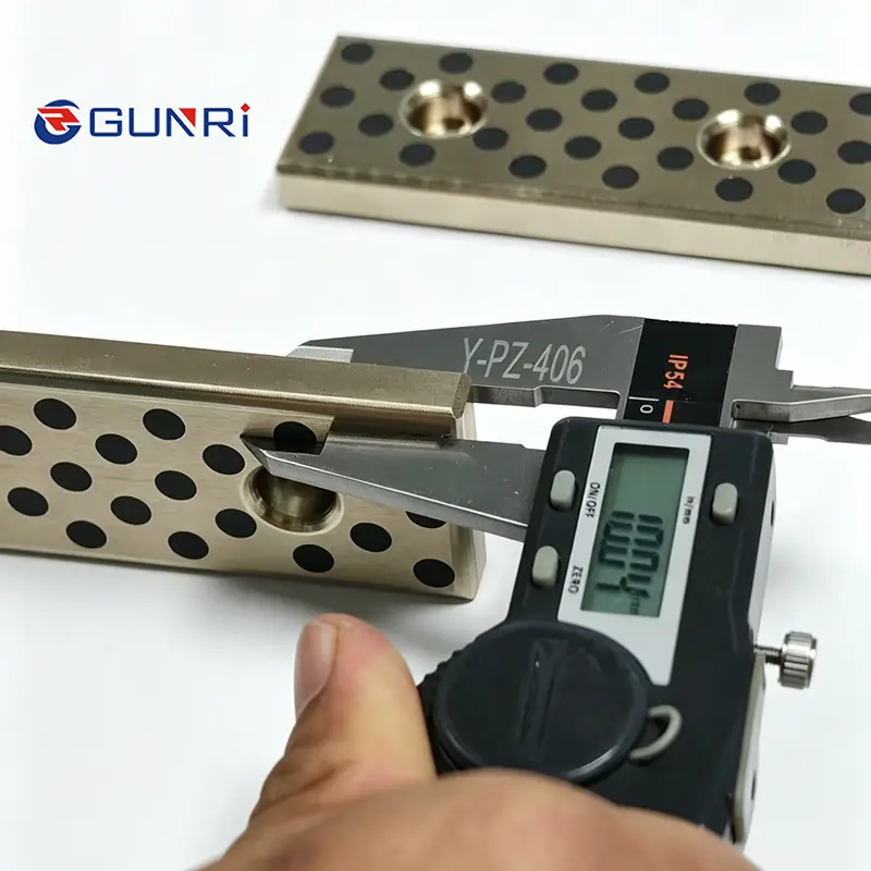
Once the source station is identified, measure the guide block clearance on all four sides using a feeler gauge. Do not rely on visual inspection — a 0.05 mm clearance gap is invisible to the naked eye but can produce measurable part deviation.
Insert the feeler gauge between the guide block and the rail at three positions along the stroke: top, middle, and bottom. Record each reading separately. If the clearance varies by more than 0.02 mm along the stroke, the wear is uneven and the block is tilting under load. This means the wear is accelerating and the guide block needs replacement before the next production run.
The acceptable clearance for most automotive progressive die guide blocks is between 0.03 mm and 0.08 mm per side. If any reading exceeds 0.10 mm, that block is a candidate for replacement. If it exceeds 0.15 mm, the block has already caused permanent positional shift in the stamped parts and must be replaced before the die runs again.
How to Replace Worn Guide Blocks and Restore Clearance
Guide block replacement requires precision in every step. The pocket in the die shoe must be clean and free of burrs. The new block must match the original dimensions — do not assume the replacement catalog part is identical. Measure the new block with a micrometer and compare it to the original drawing.
Set the initial clearance to the midpoint of the acceptable range — typically 0.05 mm per side for standard progressive dies. Use a feeler gauge to verify clearance on all four sides while the die is open. Then cycle the press at low speed for 10–20 strokes and recheck the clearance under dynamic conditions. The clearance may change slightly as the block seats against the rail under load. This dynamic check is the step most maintenance teams skip, and it is the step that catches clearance errors before they cause production problems.
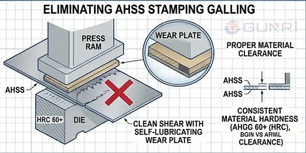
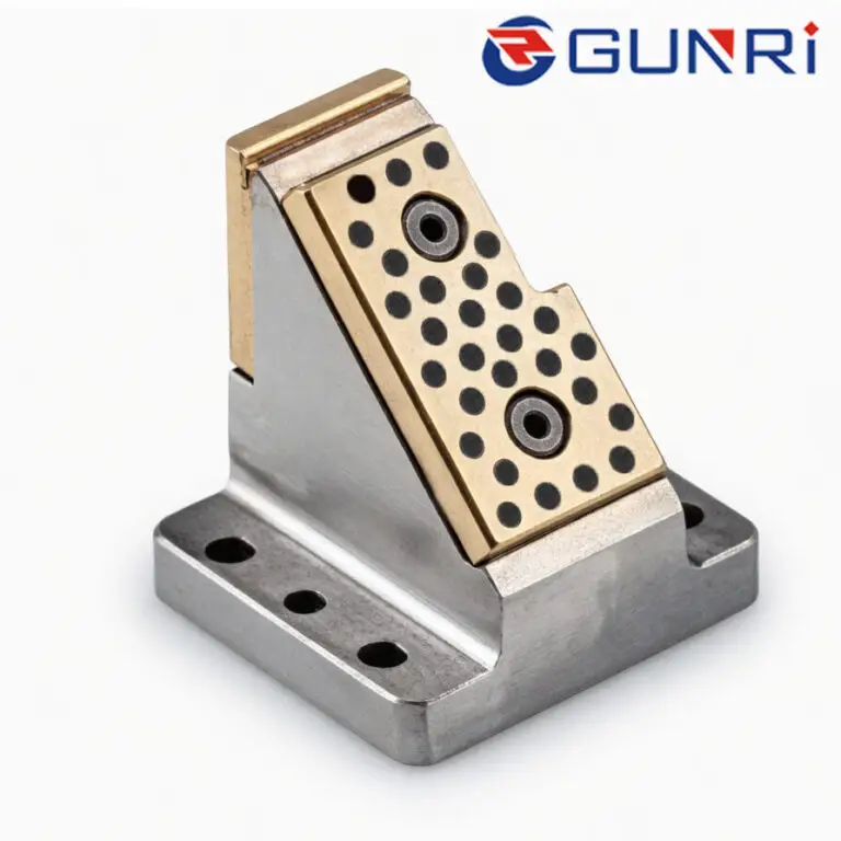
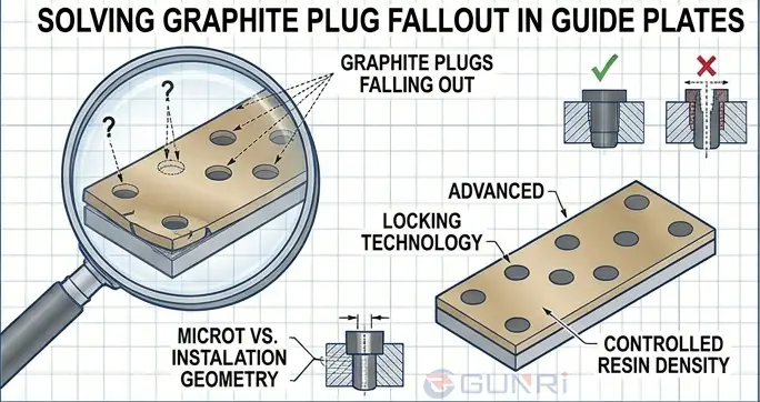
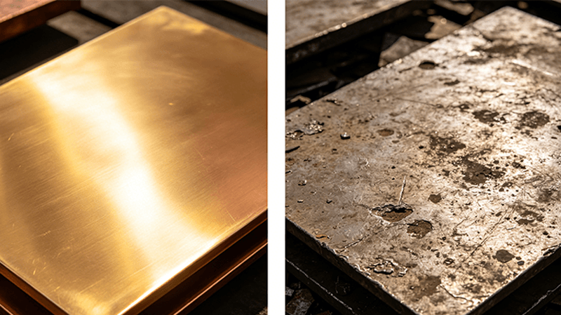
For dies that have experienced repeated guide block wear at the same station, consider upgrading the block material. Standard steel guide blocks need replacement every 6–12 months in high-cycle progressive dies running at 30+ SPM. Graphite-embedded bronze guide blocks in the same application last 18–24 months because the graphite eliminates the abrasive wear mechanism that accelerates clearance growth. The graphite plugs provide continuous solid lubrication at the sliding interface, removing the need for oil lines at the guide block location.
How to Set Up a Preventive Monitoring Plan for Guide Block Wear
The real cost of guide block wear is not the block itself — it is the cumulative cost of downtime, scrap, and troubleshooting labor that accrues before someone discovers the wear. A monitoring plan eliminates that cost.
Measure guide block clearance at every scheduled maintenance interval. Record the readings in a log or spreadsheet. If the clearance at any station increases by 0.02 mm since the last measurement, schedule replacement before the next production run — even if the clearance is still within the 0.08 mm tolerance. A 0.02 mm increase in one interval indicates that the wear rate is accelerating and the block will reach the limit before the next scheduled measurement.
Mark the initial clearance on the die shoe with a stamped reference tag next to each guide block. This gives every maintenance technician a known baseline and eliminates guesswork. Run a first-article measurement after every die setup. If the hole locations have shifted by more than 0.05 mm from the previous run, inspect the guide blocks at the source station before continuing production.
The most advanced monitoring approach is indirect: track the drive motor current trend for the press. As guide block clearance increases, the die shoe shifts under load, creating additional friction that the press motor compensates for with higher current. A gradual 3–5% increase in motor current over several weeks, with no other changes to the press settings, is often the earliest indicator of guide block wear — visible before any measurable part deviation occurs. Preventive die maintenance procedures outlined by The Fabricator emphasize that regular inspection of guide components should be part of a structured maintenance program, not a reactive response to production problems.
Frequently Asked Questions
Q: Can I adjust the guide block clearance with shims instead of replacing the block?
A: Shim adjustment is a temporary fix. Adding a shim behind the block restores clearance but does not correct the worn contact surface geometry. The worn surface will continue to wear at an accelerated rate because the remaining material is below the case-hardened depth. Replace the block at the next scheduled maintenance window.
Q: How many guide blocks in a progressive die typically need replacement at the same time?
A: In most cases, only the blocks at the source station need replacement. The other stations may still have acceptable clearance. Replace only the blocks that exceed 0.10 mm clearance. Replacing all blocks unnecessarily adds cost and changes the clearance distribution across the die, which can introduce new alignment issues.
Q: Does the guide rail also wear, or just the block?
A: Both surfaces wear, but the guide block is designed as the sacrificial component. The rail is hardened and ground, while the block is softer by design. When replacing the block, inspect the rail for scoring or galling. If the rail shows damage, it must be reground or replaced before the new block is installed. A damaged rail will accelerate wear on the new block within hours.
Q: Can graphite-embedded bronze guide blocks be retrofitted to an existing progressive die without modifying the pocket?
A: Yes, provided the pocket can accommodate the block thickness. The mounting hole pattern is standard. Remove the steel block, install the bronze block, and disconnect the grease line — the graphite plugs provide the lubrication. Many shops convert one station at a time during scheduled maintenance to spread the cost across multiple budget periods.