How to Calculate the Maximum Allowable Contact Pressure (PV Value) for NAAMS Wear Plates
I once watched a die designer spend three hours optimizing a trim steel geometry, only to see the wear plates fail within two weeks of production. His PV calculation was wrong —not the math, but the input numbers. He had used the static load instead of the dynamic load, and the result was off by a factor of 2.5. The plates overheated, the oil film broke down, and the gibs galled before the first shift was done. That is the kind of mistake that PV calculation exists to prevent —but only if you use the right numbers.
What Is PV Value and Why Does It Matter for NAAMS Wear Plates

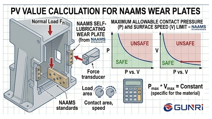
PV value is the product of contact pressure P (in MPa) and sliding velocity V (in m/s). The result, expressed in MPa·m/s, represents the intensity of the tribological contact at the wear plate interface. A higher PV value means more frictional heat generation per unit area, which determines whether the lubricant film can survive. Independent bearing manufacturers and industry references treat PV as “the single most important performance parameter for any sliding bearing or wear plate” (Tocree Engineering Guide).
NAAMS —North American Automotive Metric Standards —defines the dimensional specifications for wear plates in automotive stamping dies: length, width, thickness, and mounting hole patterns. The NAAMS standard does not specify materials or PV ratings. That decision is left to the die designer, which means the responsibility for verifying the PV value sits with you. Organizations like USCAR maintains the NAAMS specification as a collaborative standard between Chrysler, Ford, and GM.
Exceeding the PV limit follows a predictable sequence. The interface temperature rises above 80°C for steel plates or 120°C for bronze plates. The lubricant film degrades at the hot spots. Metal-to-metal contact begins at the asperity peaks. Adhesive wear (galling) initiates and accelerates. The progression from first symptom to catastrophic failure can take as little as 1,000 strokes in a high-load die. Research published in The Fabricator confirms that tool material selection directly determines galling onset under AHSS stamping conditions.
How to Calculate Contact Pressure P on a NAAMS Wear Plate
Contact pressure P is the side thrust force divided by the projected bearing area. The formula is P (MPa) = F (N) ÷ A (mm²).
The side thrust force F is typically 5—5% of the vertical press force at any given station. The highest values come from unbalanced cutting —piercing a large hole near one edge of the strip, or trimming a curved contour where the trim steel contacts on only one side. For dies where the side thrust cannot be calculated from first principles, a practical rule of thumb is to assume 10% of the press tonnage at the worst-case station.
Example: A 500-ton press with maximum side thrust of 50 tons (490 kN), distributed across four NAAMS GBB-20-100 wear plates. Each plate is 100 mm × 50 mm = 5,000 mm². Total area = 20,000 mm². P = 490,000 ÷ 20,000 = 24.5 MPa.
Static vs dynamic load —a critical distinction. The static load capacity of a wear plate (die closed, not sliding) can reach 2— times the dynamic capacity. Graphite-embedded bronze plates handle static loads up to 80—00 MPa for CuSn12 tin bronze, but the dynamic sliding limit for the same material is 20—0 MPa. Always use the dynamic pressure for PV calculation. Using the static rating will underestimate the real contact stress by a factor of 2—.
How to Calculate Sliding Velocity V in a Press
The sliding velocity V is the speed at which the wear plate moves across the mating gib. The formula is V (m/s) = (2 × stroke length in meters × SPM) ÷ 60.
The factor of 2 accounts for both the downstroke and the upstroke. For a press at 15 SPM with 300 mm stroke: V = (2 × 0.3 × 15) ÷ 60 = 0.15 m/s.
This formula gives the average velocity. The instantaneous mid-stroke velocity on a mechanical press is approximately 1.57 times higher, due to the sinusoidal motion profile. For presses running above 30 SPM, the difference between average and peak velocity becomes significant. For servo presses with programmable motion, use the programmed sliding speed directly from the control parameters.
Why Checking the PV Product Alone Is Not Enough —Check P and V Independently
Multiply P by V to get the PV value. Using the example above: P = 12 MPa, V = 0.15 m/s, PV = 1.8 MPa·m/s.
Here is a trap I see regularly in die design reviews. The PV product compares favorably to the material limit, so the engineer approves the design. But one of the individual parameters —P or V —exceeds its independent limit, and the plate fails. WS Hampshire’s technical note on PV values makes this explicit: “Pressure and Velocity are separate and distinct functions. Some materials excel at high load, low speed applications, while others perform best in low load, high speed applications.”
A steel wear plate rated at 1.8 MPa·m/s with a P limit of 15 MPa and a V limit of 0.3 m/s could pass the PV check at P = 18 MPa and V = 0.1 m/s (PV = 1.8) —but the P limit of 15 MPa is exceeded. The plate will fail regardless of the PV value.
Always verify P against the maximum allowable dynamic pressure AND V against the maximum allowable sliding velocity before comparing the PV product to the rated limit. This three-step check —P independently, V independently, PV as the product —eliminates the single most common cause of premature wear plate failure in stamping dies.
PV Material Limits Comparison: Steel vs Bronze vs Bimetallic
The rated PV limit depends on the material, lubrication method, counterface finish, and operating temperature. The table below provides typical values for NAAMS wear plate materials under standard conditions (Ra 0.4 µm counterface, 25°C ambient, continuous operation). These values are compiled from published manufacturer data and industry PV reference tables.
| Material | Lubrication | Max PV (MPa·m/s) | Max Dynamic P (MPa) | Max V (m/s) | Friction Coefficient |
|---|---|---|---|---|---|
| Hardened tool steel (58—2 HRC) | Oil | 1.5—.0 | 10—5 | 0.3 | 0.10—.15 (with oil) |
| Case-hardened steel 16MnCr5 | Oil | 1.2—.8 | 10—2 | 0.3 | 0.12—.18 (with oil) |
| Tin bronze CuSn12 + graphite | Self-lubricating | 3.5—.0 | 15—5 | 0.5 | 0.08—.12 |
| Aluminum bronze CuAl10Ni5Fe4 + graphite | Self-lubricating | 4.0—.5 | 20—0 | 0.5 | 0.08—.12 |
| Bimetallic (steel + bronze + graphite) | Self-lubricating | 4.5—.0 | 20—0 | 0.6 | 0.08—.12 |
| High-leaded bronze SAE 841 | Oil-impregnated | 2.0—.0 | 8—2 | 0.4 | 0.12—.20 |
Note on data variation between suppliers. Different manufacturers use different test protocols. A supplier claiming 5.0 MPa·m/s for graphite bronze may be testing at a different counterface hardness or surface finish than one claiming 3.5 MPa·m/s. When comparing supplier data, always request the test conditions: counterface hardness, surface finish, ambient temperature, and failure criterion. DME’s wear plate FAQ recommends at least 6- HRc hardness difference between the plate and the mating surface for optimal performance, a detail that is rarely included in supplier PV ratings.
NAAMS Plate Sizes and Their PV Capacity —Pre-Calculated Reference Table
The table below gives pre-calculated PV values for standard NAAMS wear plate sizes at different side thrust levels. This allows a quick initial check before running the full calculation. Values assume 2 plates per station and V = 0.15 m/s (15 SPM, 300 mm stroke).
| NAAMS Part | Size (mm) | Area per Plate (mm²) | PV @ 50 kN (MPa·m/s) | PV @ 100 kN | PV @ 200 kN |
|---|---|---|---|---|---|
| GBB-12-75 | 75 × 50 | 3,750 | 1.0 | 2.0 | 4.0 |
| GBB-16-75 | 75 × 75 | 5,625 | 0.67 | 1.33 | 2.67 |
| GBB-20-100 | 100 × 50 | 5,000 | 0.75 | 1.50 | 3.00 |
| GBB-25-125 | 125 × 75 | 9,375 | 0.40 | 0.80 | 1.60 |
| GBB-32-150 | 150 × 100 | 15,000 | 0.25 | 0.50 | 1.00 |
| GBB-40-200 | 200 × 100 | 20,000 | 0.19 | 0.38 | 0.75 |
Bold values in the table indicate where standard steel plates would exceed their 2.0 MPa·m/s limit. At 200 kN side thrust on a GBB-12-75, the PV reaches 4.0 —only graphite-embedded bronze or bimetallic plates can handle this without galling. For reference, Danly IEM’s wear products catalog provides individual load ratings for their wear plate series, which can be used to cross-check these calculated values against physical test data.
Safety Factors and Real-World Temperature Verification
Laboratory PV limits assume perfect alignment, clean surfaces, and controlled temperature. Real stamping dies operate with misalignment, contamination, and thermal cycling. Industry practice is to apply a safety factor of 1.5—.0 to the calculated PV before comparing it to the material limit.
For the example with PV = 1.8 MPa·m/s and a safety factor of 1.5, the design PV is 2.7 MPa·m/s. This exceeds the steel limit of 2.0 but sits comfortably within the graphite-embedded bronze limit of 5.0.
The most reliable verification method is temperature measurement. Run the die for 30 minutes at full production speed. Measure the wear plate surface with a contact thermocouple or thermal camera. For steel plates, the surface should stay below 80°C. For graphite-embedded bronze, the limit is 120°C. A temperature reading above these thresholds indicates PV overload regardless of what the calculation says. A 10°C increase above baseline is a warning. A 20°C increase means the limit has been exceeded and corrective action is needed.
How to Retrofit a Die When the PV Value Exceeds the Steel Limit
When the calculated PV exceeds the steel plate limit, the conventional fix is to redesign the die —larger plates, additional guide pillars, or reduced speed. These options are expensive. A simpler alternative is to change the plate material while keeping the same die geometry.
A transfer die running door inner panels was designed with hardened steel wear plates at a calculated PV of 1.8 MPa·m/s. The first set galled within 3 months. The pocket dimensions were fixed and could not be modified. The solution was a direct retrofit: replace the steel plates with graphite-embedded tin bronze plates of the same NAAMS size. The bronze provided a PV limit of 5.0 MPa·m/s —a 2.8× safety margin over the 1.8 MPa·m/s demand. The plates have been in service for over 18 months with no galling.
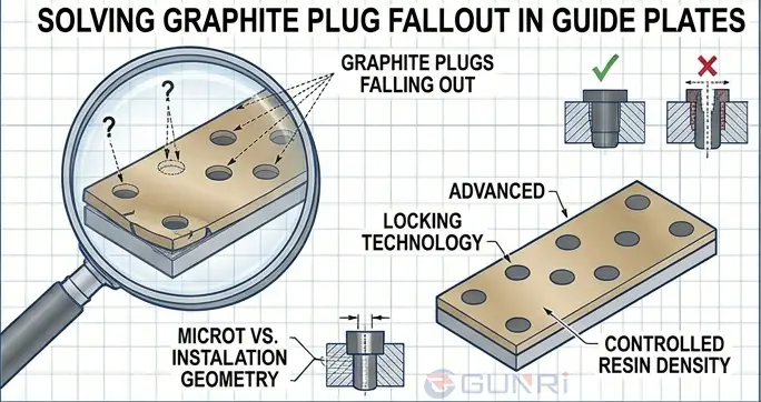
The retrofit process takes 30—5 minutes per station: remove the old plates, clean the pockets, install the bronze plates with the same bolt pattern, and disconnect the grease lines. The graphite plugs eliminate the need for oil distribution entirely.
Frequently Asked Questions
Q: What happens if the PV value exceeds the material limit?
A: The plate overheats, the lubricant breaks down, and galling initiates within hours if the excess is 20% or more. Fix it by reducing P (increase bearing area), reducing V (lower press speed), or switching to a higher-PV material like graphite-embedded bronze.
Q: Does the NAAMS standard guaranteee the PV is acceptable for any application?
A: No. NAAMS specifies dimensions only —not materials, loads, or performance. A NAAMS GBB-20-100 in a low-load station might last years. The same plate under high side thrust without PV verification may fail in weeks.
Q: How does counterface surface finish affect the PV limit?
A: A plate running against Ra 0.8 µm can handle about 30% less PV than the same plate against Ra 0.4 µm. The rougher surface creates higher localized contact pressures at the asperity peaks, initiating galling earlier. DME recommends Ra 0.4 µm or better for the mating surface.
Q: Can I compare different suppliers using their published PV values?
A: With caution. A supplier claiming 5.0 MPa·m/s may only deliver 3.0 under your actual conditions. Request their test protocol: counterface finish, ambient temperature, and failure criterion. Cross-check their number against the comparison table in this article.