Why Do Automotive Stamping Die Cam Sliders Seize Under High-Cycle Production?
Last month, a production manager called me mid-shift with that tone you learn to recognize. His progressive die for a body panel was running at 35 strokes per minute when the cam slider locked up solid. The die had to be pulled, the press line went dark for six hours, and the repair bill punched a hole in his quarterly numbers. He had two questions: why did this happen, and will it happen again? That call is half the reason I’m writing this article. The other half is that I’ve seen the same pattern repeat across too many shops.
Cam sliders seize under high-cycle production because three distinct failure modes converge as stroke count increases: lubrication film breakdown, thermal expansion overload, and gib clearance wear. These three mechanisms do not act independently. They feed each other in a cycle that, once started, accelerates toward catastrophic seizure in a matter of thousands of strokes. Understanding how each one works and how they compound is the only way to prevent the next downtime event.
How a Cam Slider Unit Works — and Where It Breaks
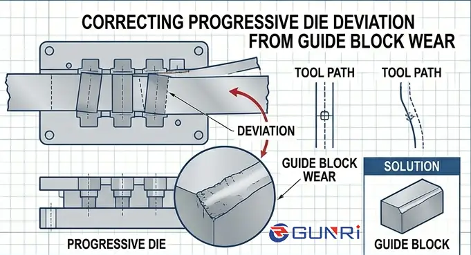
A cam slider in a stamping die converts the vertical motion of the press into horizontal or angled movement using a driver wedge that pushes against an angled slide. The slide travels on wear plates (gibs) and returns via mechanical springs or nitrogen gas springs. At 30–50 strokes per minute in an automotive application, this interface experiences hundreds of thousands of reciprocating cycles per week. Each cycle generates friction, heat, and microscopic wear debris. Over time, those byproducts become the root cause of failure.
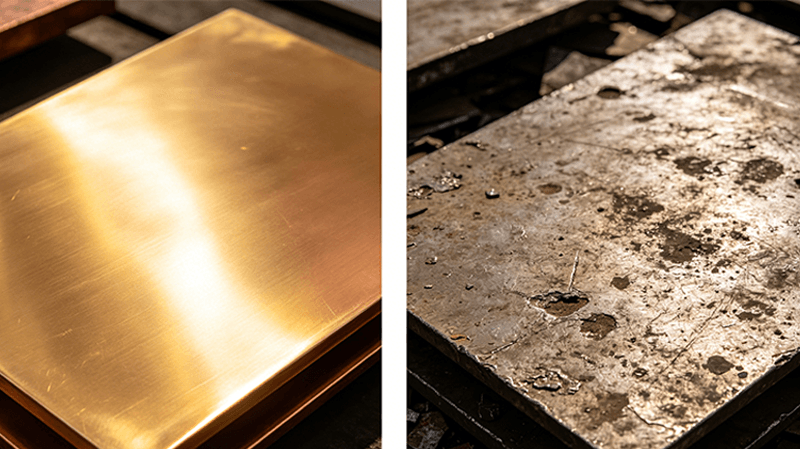
According to die design expert Art Hedrick of Dieology LLC, the single most fundamental rule for cam slides is to use dissimilar metals for mating wear surfaces. When both the cam and the driver are made of the same tool steel (such as D2 or A2 running against itself), adhesive galling becomes nearly inevitable under high-contact pressure. The metallurgical similarity allows microwelds to form between opposing asperities, and the resulting cold welding pulls material from one surface and deposits it on the other. That transfer layer grows until it jams the slide.
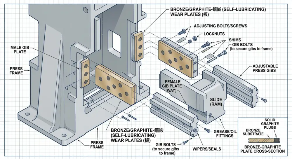
As Hedrick explains in The Fabricator, aluminum bronze such as Ampco 18 or Ampco 21 with graphite plugs is a proven countermeasure. The bronze provides a different crystal structure that resists adhesive transfer, and the graphite acts as a dry-film lubricant even when liquid lubricant is squeezed out. However, he cautions against using heavy grease on graphite-inserted plates because the suction can pull the graphite out of its pockets. Light oil only.
Failure Mode #1: Lubrication Film Breakdown at High Cycle Rates
In a properly designed cam slider, a thin boundary layer of lubricant separates the sliding surfaces. At low cycle rates (5–15 SPM), this film has time to recover between strokes. As cycle rates push past 25–40 SPM in modern automotive press lines, the recovery window shrinks. The lubricant film thins, local hot spots develop, and boundary lubrication transitions to mixed or dry contact.
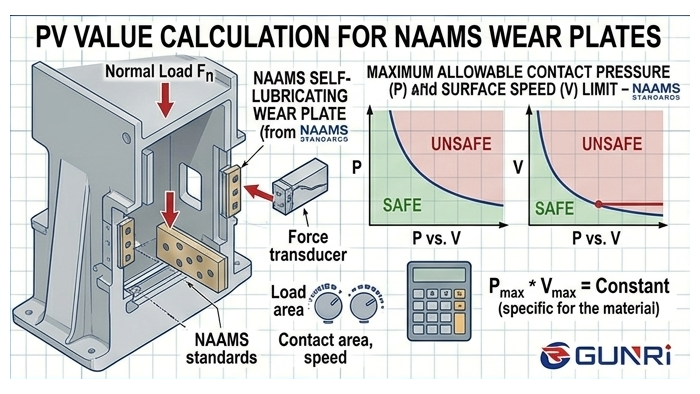
Research from Oakland University’s CAMM lab on galling onset in aluminum stamping showed that contact pressure of 30 MPa or higher dramatically accelerates lubricant film failure. At 40 MPa, galling began within a few dozen cycles under dry conditions, while adding proper lubricant raised the threshold but did not eliminate it. The same principle applies to cam slider wear plates. When contact pressure exceeds the film strength of the lubricant, metal-to-metal contact occurs, generating frictional heat that further degrades the remaining lubricant.
For high-cycle automotive dies, minimum quantity lubrication (MQL) systems or self-lubricating wear plate materials like graphite-embedded bronze offer a more reliable long-term solution than relying on manually applied grease alone. The key requirement is that the lubrication mechanism must be continuous and cannot depend on operator intervention between shifts.
Failure Mode #2: Thermal Expansion Overload
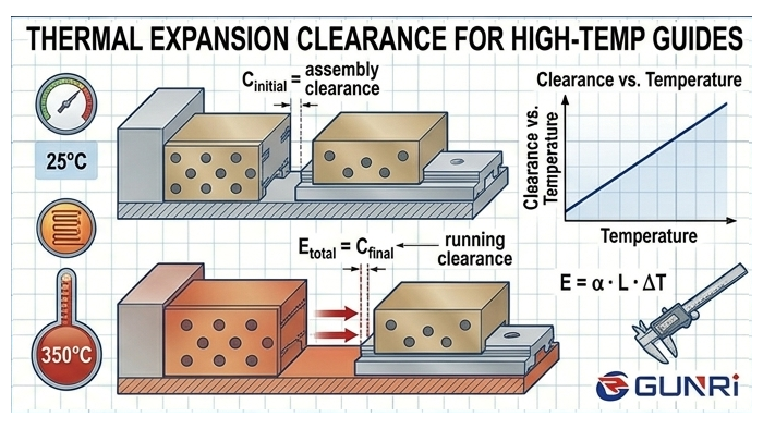
When the lubricant film fails, friction rises sharply. The energy that was previously dissipated as fluid shear is now converted into heat at the sliding interface. A steel cam slider has a coefficient of thermal expansion of roughly 12 × 10⁻⁶ /°C. A 50°C temperature rise on a 300 mm slide produces approximately 0.18 mm of linear expansion. When the initial clearance between the cam and its gibs is designed at 0.05–0.08 mm, that 0.18 mm expansion does not simply reduce clearance — it eliminates it entirely and creates interference.
Once interference occurs, the heat generation rate increases exponentially because the sliding surfaces are now in contact under load across their entire face. More friction produces more heat, more expansion produces tighter interference, and the system enters thermal runaway. This is the mechanism that produces the classic seized cam slider that cannot be moved even after the die has been pulled from the press and allowed to cool.
Die protection systems using inductive sensors can detect a cam that is not returning fully before the next press stroke. While this does not prevent thermal expansion, it stops the press before a full seizure causes catastrophic die damage. The cost of these sensors is trivial compared with a die rebuild.
Failure Mode #3: Gib Clearance Wear and Contamination Trapping
Even with good lubrication and controlled thermal conditions, wear plates lose material over time. In a progressive die running at high cycle rates, the gib surfaces accumulate wear debris from both the cam slider and the stamping process itself. Fine metal particles from piercing and blanking operations settle on the wear plates. Mixed with residual lubricant, this forms a lapping compound that accelerates abrasive wear.
As the gib clearance increases beyond the design tolerance of 0.05–0.10 mm, the cam slider loses its precision guidance. It begins to tilt and side-load under the cutting forces. This uneven loading concentrates contact pressure on a smaller area, which leads to localized galling. Once galling begins, the damaged surface profile generates peaks that dig into the mating surface. The cam becomes progressively harder to move during each stroke until it locks.
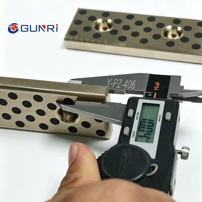
Dayton Lamina, a major cam unit manufacturer, specifies that standard cam slide clearance should be maintained between 0.05 mm and 0.10 mm for typical automotive applications. Once clearance exceeds 0.15 mm, the risk of side-loading-induced seizure increases significantly. Regular clearance checks at every scheduled die maintenance interval — not just when a problem appears — is the only reliable way to catch wear before it becomes a failure.
How Nitrogen Gas Springs Affect Cam Return Reliability
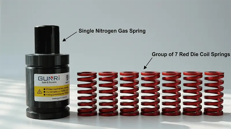
Cam return mechanisms play an indirect but important role in seizure prevention. A cam that does not fully retract on the return stroke will be struck by the driver on the next down stroke, generating a lateral impact load that can bend slide components or displace wear debris into the clearance gap. Mechanical coil springs fatigue and lose preload over time, especially at high cycle rates, which reduces return force and leaves the cam partially extended.
Nitrogen gas springs maintain consistent return force throughout the stroke and do not fatigue like mechanical springs. They provide a positive return that ensures the cam retracts fully before the next cycle. For high-cycle automotive dies, replacing mechanical return springs with nitrogen gas springs is a retroactive upgrade that directly reduces seizure risk by eliminating one variable in the failure chain.
Preventive Strategies That Address All Three Modes
Based on the failure mechanisms above, a comprehensive prevention program for cam slider seizure should include the following elements:
- Dissimilar materials — use aluminum bronze wear plates against hardened tool steel cam slides. Avoid identical tool steel combinations.
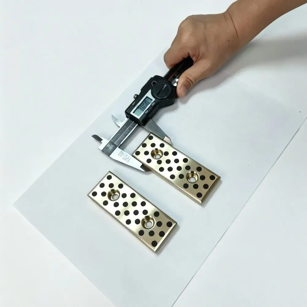
- Self-lubricating wear plate materials — graphite-embedded bronze or sintered bronze with oil retention provides continuous lubrication that does not degrade at high cycle rates.
- Controlled clearance monitoring — inspect gib clearance at every maintenance interval. Replace wear plates before clearance exceeds 0.12 mm.
- Nitrogen gas spring return — upgrade from mechanical springs to nitrogen gas springs to ensure consistent full retraction at every cycle.
- Die protection sensors — install inductive proximity sensors to detect incomplete cam return before the next stroke.
- Lubrication system verification — use MQL or automated lubricant delivery rather than manual application.
Each of these strategies is individually useful, but their real power comes from working together. A self-lubricating bronze plate with proper clearance and a nitrogen return system will outlast a conventional steel-on-steel design by a factor of three to five in high-cycle production — and it will eliminate the sudden seizure failures that cost production lines their most expensive resource: uptime.
Frequently Asked Questions
Q: Can I retrofit an existing die with self-lubricating wear plates?
A: Yes, if the die’s existing gib pockets have sufficient material to machine new pockets for bronze wear plates. The typical retrofit involves removing the existing steel gibs, machining the pocket to standard thickness, and installing graphite-embedded bronze wear plates with the same mounting hole pattern. Expect 8–12 hours of bench time for a typical progressive die cam station.
Q: How often should cam slide clearance be checked?
A: For high-cycle automotive dies (running 5+ days per week), clearance should be checked every 100,000 strokes or at each scheduled die maintenance interval, whichever comes first. Use a feeler gauge at the mid-point of the slide travel with the cam at mid-stroke.
Q: What is the maximum acceptable temperature rise for a cam slider in operation?
A: A temperature rise of 20–30°C above ambient is normal for a well-lubricated cam at 30 SPM. Any reading above 50°C differential indicates incipient lubrication failure and should trigger immediate inspection. Infrared thermography during a production run is the fastest way to scan all cam stations.
Q: Are coated wear plates (TiN, DLC) better than bronze?
A: Coatings reduce wear but do not eliminate the need for dissimilar material interfaces. TiN-coated tool steel running against uncoated tool steel still risks adhesive galling if the coating wears through at high-stress points. A bronze wear plate with graphite plugs provides bulk material compatibility that coatings alone cannot guarantee. For maximum life, combine a coating on the cam slide with a bronze gib plate.
Q: Does using a higher-viscosity lubricant help prevent seizure?
A: Higher viscosity improves film thickness at low temperatures but may not flow into the clearance gap at startup. A better approach is to use a lubricant with extreme pressure (EP) additives designed for sliding wear interfaces, such as those containing molybdenum disulfide or zinc dialkyldithiophosphate (ZDDP). These additives bond to the metal surface and provide a sacrificial layer that protects even when the liquid carrier is displaced.