Needle Roller Guide: Technical Analysis and Custom Project Guide
In high-end precision dies, semiconductor automation equipment, and optical inspection instruments, the guide components directly determine positioning accuracy and system rigidity. When faced with high-speed cycling, heavy loads, or micron-level tolerances, conventional round guide posts, ball guide posts, and ball splines often show limitations — elastic deformation under side loads, or fretting wear over time.
Needle roller guide sets — also referred to as polygon linear needle guides, roller guide post sets, or MILLION GUIDE-type units — address these limitations through multi-surface line-contact design. This article breaks down the structure, performance characteristics, and practical considerations for engineers evaluating or specifying these components.
1. Structure and Working Principle
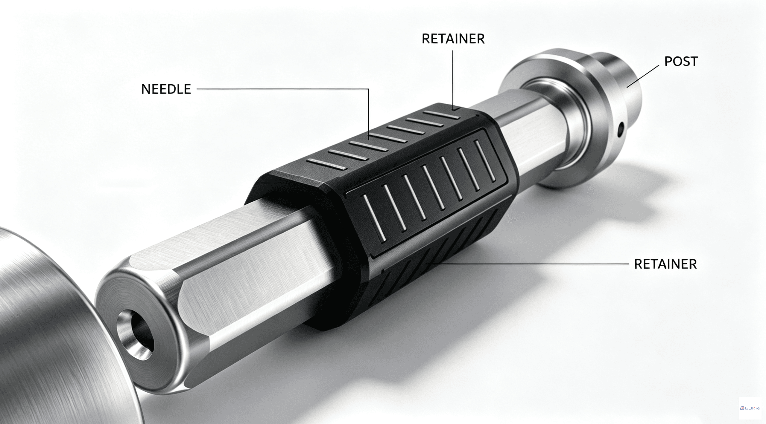
Unlike conventional round guide posts, a needle roller guide assembly consists of three precision-matched components:
- Polygon Post. The shaft is precision-ground using multi-axis CNC profile grinders to form symmetrical polygon flats — each face acting as a precision raceway.
- Needle Rollers. The rolling elements use line contact rather than the point contact of ball bearings. This increases the effective load-bearing surface area substantially.
- Retainer (Cage). Positions the needle rollers uniformly and constrains their motion path, ensuring stability during high-speed reciprocation.
2. How It Compares to Other Guide Types
| Guide Type | Contact Method | Key Limitation |
|---|---|---|
| Round Plain Guide | Sliding surface contact | Wear increases clearance over time; prone to scoring under heavy loads |
| Ball Spline / Ball Guide | Point contact (balls) | Lower impact resistance; brinelling (surface indentations) under sustained heavy loads |
| Needle Roller Guide | Line contact (rollers) on polygon surfaces | Higher manufacturing cost; requires precision alignment during installation |
The polygon needle roller guide combines multi-surface engagement with line-contact rolling. This gives it a stiffness profile closer to a plain guide while retaining the low friction of a rolling-element design — something neither ball guides nor plain guides can achieve simultaneously.
3. Key Performance Metrics
When evaluating a needle roller guide for a specific application, these are the specifications that matter:
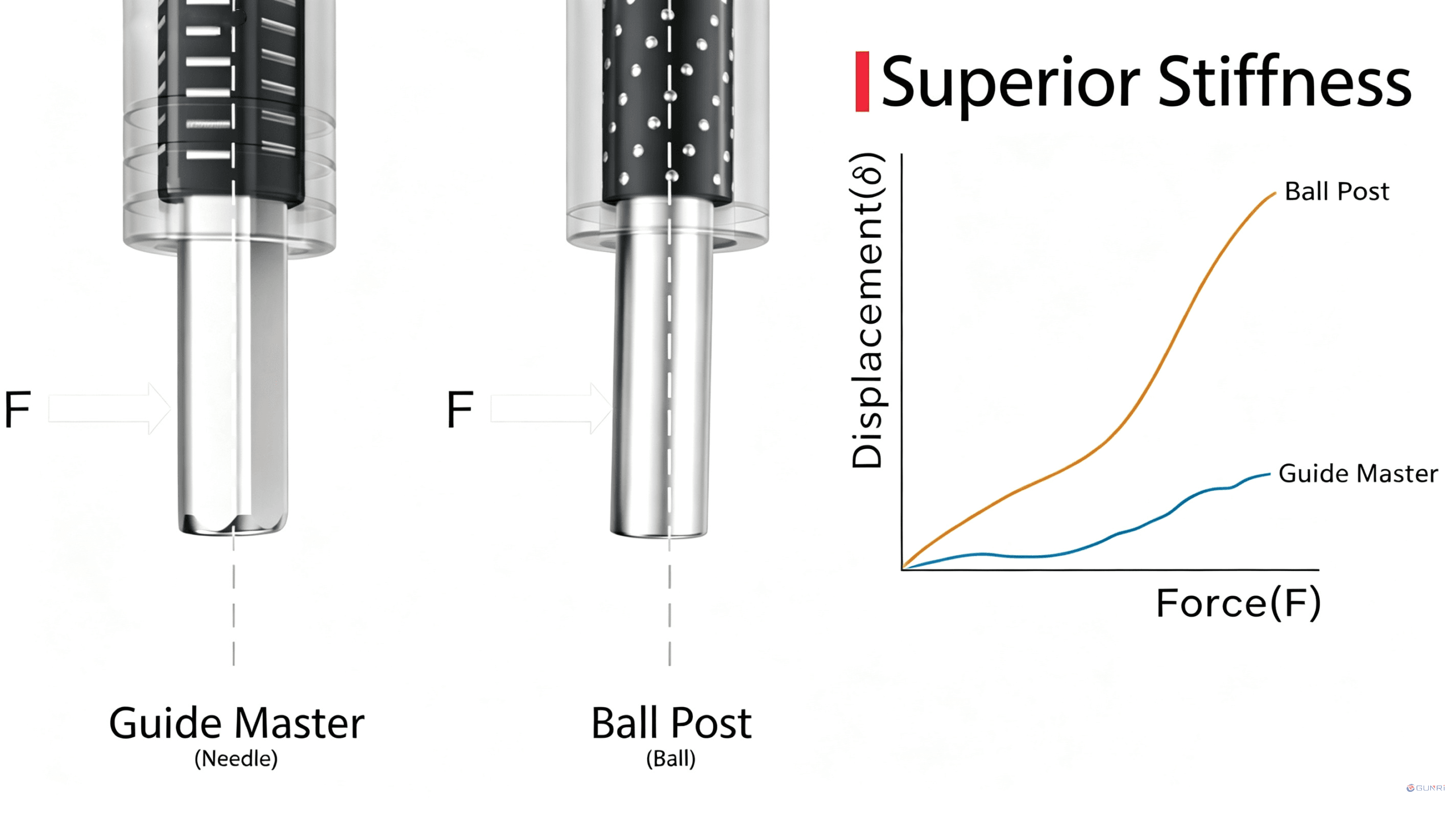
- Stiffness. Under alternating side loads — common in stamping dies and high-speed pick-and-place — a needle roller guide exhibits minimal elastic deformation. This suppresses micro-displacement and vibration during direction changes.
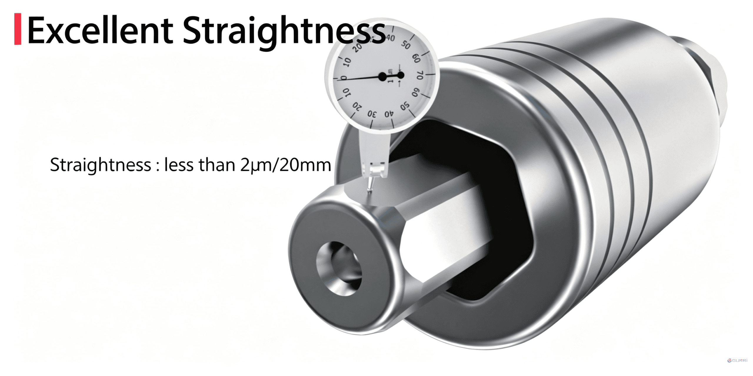
- Straightness. The polygon post is typically ground to a straightness of < 2 µm per 20 mm of travel. Clearance remains uniform across the full stroke.
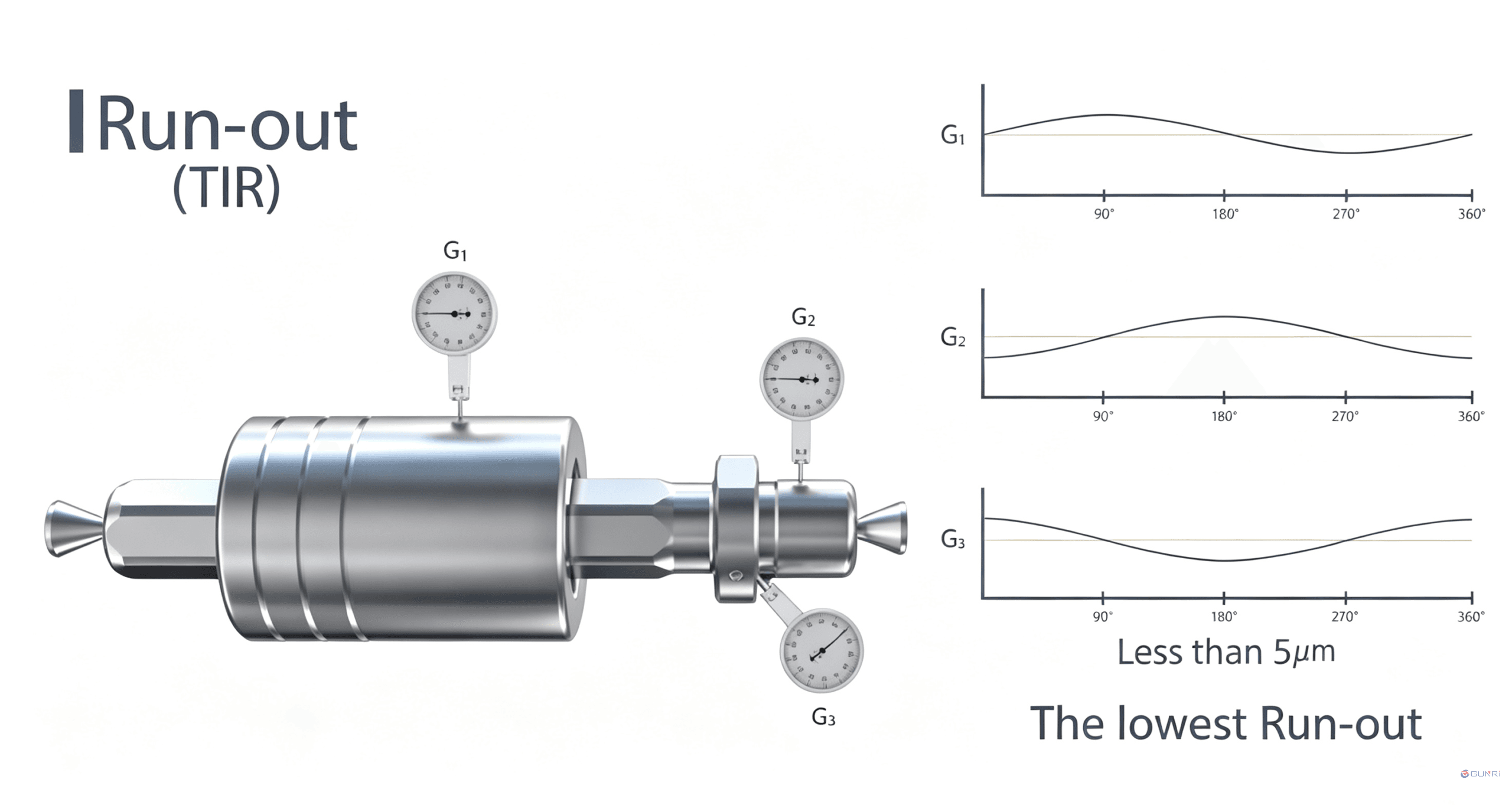
- Radial Run-out (TIR). Total indicated run-out is held to within 5 µm in precision-grade assemblies. This keeps the motion path error low and supports repeatable positioning.
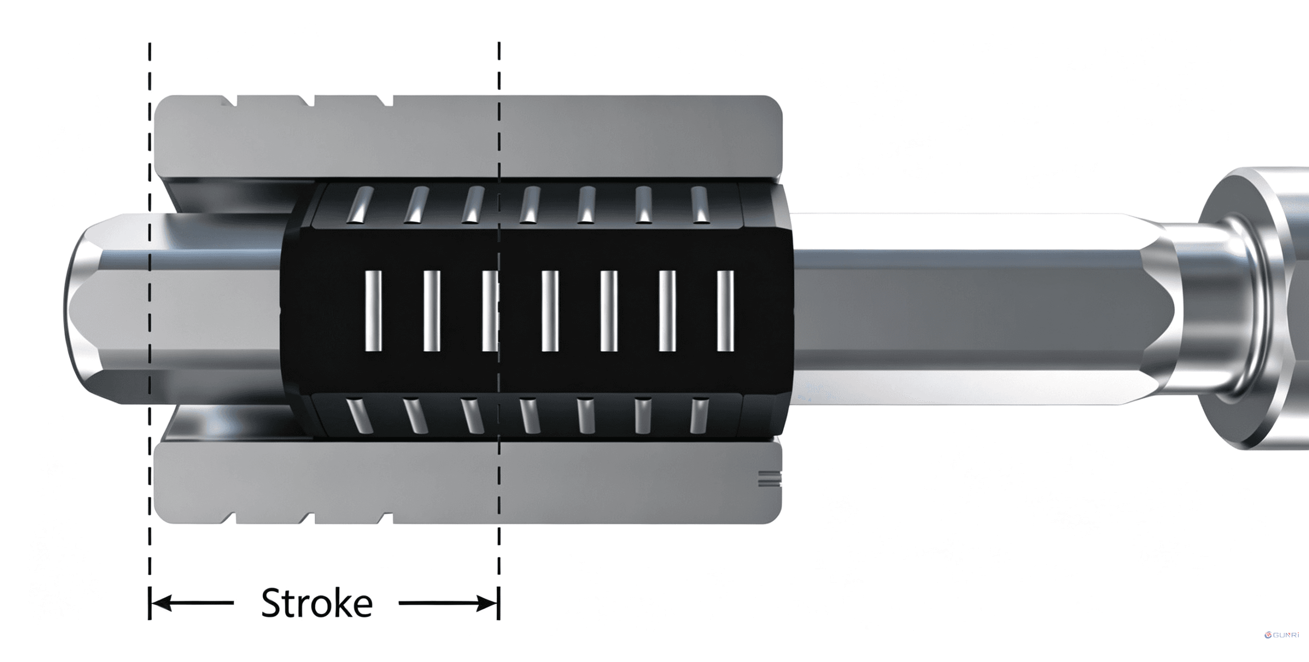
- Effective Stroke. Determined by the retainer’s working range. The needle rollers must remain fully engaged throughout the stroke — insufficient engagement length causes a sharp drop in performance.
- Surface Finish. Raceway surfaces are finished to sub-micron roughness. Lower friction means smoother operation, less heat generation, and quieter running.
4. Combined Linear and Rotary Motion
In many automated applications — robotic arms, semiconductor handling axes, optical inspection stages — the component must handle both linear travel and rotational torque simultaneously. Ball splines have traditionally served this role. Needle roller guides offer an alternative with three advantages:
- Higher load capacity. Line contact supports higher static and dynamic loads than point contact, with better resistance to impact and fretting.
- Better space efficiency. The polygon geometry delivers higher torsional rigidity within the same envelope compared to a ball spline of equivalent diameter.
- Longer precision retention. Lower wear rates under continuous operation extend the interval between major maintenance.
5. Typical Applications
- Ultra-precision dies: High-end connector progressive dies, optical component molds, smartphone lens molds.
- Semiconductor and electronics: Wafer handling robot arms, high-precision dispensing machines, semiconductor packaging and test linear modules.
- Optical inspection and automation: CMM auxiliary guidance mechanisms, optical sorters, precision linear stages.
6. Custom Manufacturing With GUNRI
Sourcing from established Japanese or European brands often means long lead times and premium pricing. For engineers working on cost-sensitive projects or non-standard designs, GUNRI offers a factory-direct alternative:
- Quality standards: GUNRI uses multi-axis optical profile grinders and optical inspection. Straightness, run-out, and hardness specifications meet international-grade benchmarks.
- Cost structure: As a source factory, GUNRI eliminates distribution layers. This can reduce BOM costs significantly compared to equivalent imported brands.
- Custom specifications: GUNRI supports non-standard dimensions, custom materials, and special operating condition requirements based on customer drawings or load/stroke specifications.
If you have a project that needs evaluation, contact GUNRI for technical support and sample testing.