How to Optimize Graphite Plug Size and Density to Maximize Bronze Wear Plate Service Life
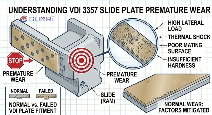
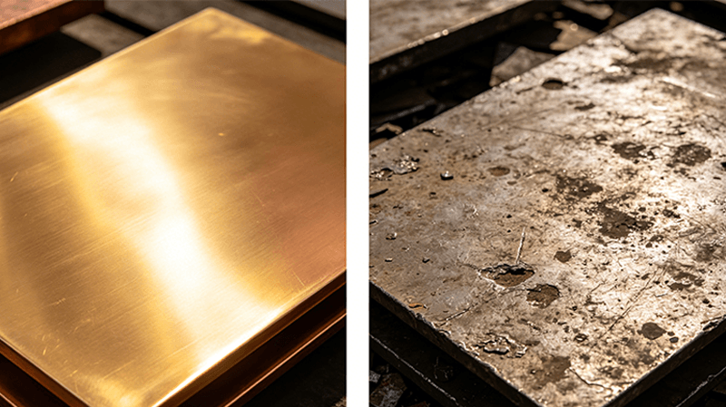
A mold designer from a German automotive stamping plant called about premature wear on a set of C95400 bronze wear plates in a progressive die. The plates had 4 mm diameter graphite plugs at 20 percent density. The die ran 200,000 strokes per month. At 12 months, the plugs were completely depleted and the bronze surface was galling against the steel slide. He asked: “Should I use bigger plugs or more plugs?”
The solution in many cases is a direct retrofit: replace the steel plates with graphite-embedded bronze wear plates of the same NAAMS size.
The short answer is both — but the correct combination depends on three variables: plug diameter, surface coverage density, and plug depth. The graphite plug configuration in a bronze wear plate is a engineered trade-off between lubrication supply and structural strength. Getting it right doubles the service life over a standard configuration.

The Three Variables of Graphite Plug Configuration
Graphite plugs in a bronze wear plate serve one function: they supply a continuous layer of solid lubricant to the sliding interface. As the plate moves, graphite transfers from the plugs to the mating surface, forming a thin film that prevents metal-to-metal contact. The plug configuration determines how long this lubricant supply lasts and how effectively it is distributed across the sliding surface.
The three variables are plug diameter, surface coverage density, and plug depth.
Plug diameter controls the volume of graphite available per plug. A 4 mm plug contains 16 percent of the volume of an 8 mm plug at the same depth. Larger plugs provide more lubricant reserve but reduce the bronze area available to carry the load.
Surface coverage density is the percentage of the wear plate face area occupied by graphite. Tocree’s engineering guide on graphite bronze wear plates states the optimum coverage range is 20 to 35 percent. Bronzebush’s best-practice guide for rolling mill bearings specifies 28 to 30 percent coverage with high-density graphite. Bronzeoilless publishes a wider range of 25 to 45 percent.
Plug depth determines the total lubricant volume and therefore the service life. Standard plug depth is 6 to 12 mm for wear plates 15 to 25 mm thick. The minimum remaining bronze thickness below the plug bottom should be 4 mm for structural integrity.
The National Bronze Enduralube process forces graphite into drilled holes under extreme pressure, ensuring that the graphite fills the full depth of the hole without voids. This mechanical insertion method produces better plug density and consistency than gravity-fed or loose-fit graphite rods.
Choose Plug Diameter Based on Plate Thickness and Load
The plug diameter should scale with the wear plate thickness. A general rule established by industry practice is that plug diameter should be 40 to 60 percent of the plate thickness.
For a 10 mm thick wear plate, use 4 to 6 mm diameter plugs. For a 20 mm thick plate, use 8 to 12 mm diameter plugs. For a 25 mm thick plate, use 10 to 14 mm diameter plugs.
For high-load applications where the bearing pressure exceeds 30 MPa, use the larger end of the diameter range. The larger plugs distribute the graphite transfer film over a wider area, reducing the peak contact stress on the bronze between plugs.
Bronzebush’s best-practice recommendation for high-temperature rolling mill bearings is 8 to 12 mm diameter plugs with high-density graphite at 1.75 g/cm³ minimum density. Smaller plugs below 6 mm diameter are not recommended for heavy industrial applications because the graphite volume per plug is too small to provide adequate lubricant supply between maintenance intervals.
The spacing between plugs should be 1.5 to 2.5 times the plug diameter, center to center. Closer spacing reduces the bronze web between plugs below the minimum recommended 3 mm, which can cause the bronze to crack under load. Wider spacing creates gaps in the lubricant film that lead to localized galling.
Set Plug Density Based on Duty Cycle and Sliding Speed
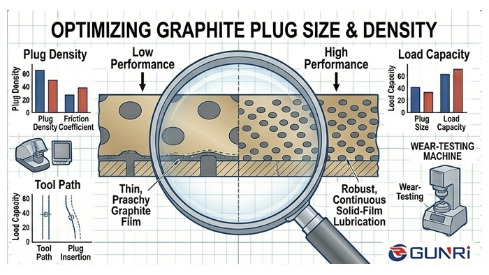
The surface coverage density — the percentage of the wear plate face occupied by graphite — is the single most important factor affecting the service life of the plate.
For light-duty applications with low loads and sliding speeds below 0.1 m/s, 20 to 25 percent graphite coverage is sufficient. These applications include mold slides, guide rails in packaging machinery, and light conveyor systems.
For medium-duty applications with moderate loads and sliding speeds of 0.1 to 0.5 m/s, 25 to 35 percent coverage is the standard range. This covers most industrial wear plate applications including press tool guides, injection molding machine slides, and heavy conveyor wear strips.
For heavy-duty applications with high loads exceeding 30 MPa or sliding speeds above 0.5 m/s, 35 to 45 percent coverage is recommended. These include rolling mill guides, offshore crane sliding pads, and large press gibs.
The practical limit is 45 percent coverage. Above this, the bronze matrix between plugs becomes too narrow to carry the structural load. The web thickness between adjacent plugs drops below 3 mm, and the plate can crack under impact or high static load. Tocree specifically warns that exceeding 50 percent graphite coverage compromises the load-bearing capacity of the bronze base.
The duty cycle also affects the required plug depth. For a given coverage percentage, deeper plugs provide more lubricant volume and longer service life. A standard 8 mm deep plug at 30 percent coverage provides approximately 5,000 hours of sliding life at 0.3 m/s sliding speed before the graphite is 50 percent depleted.
A real case: a progressive die wear plate originally specified at 20 percent coverage with 4 mm plugs lasted 12 months. After redesigning to 35 percent coverage with 8 mm plugs at the same plug depth, the replacement interval extended to 36 months. The additional graphite volume was 3.5 times the original, which matched the service life improvement.
Position the Plug Pattern Relative to Sliding Direction
The arrangement of graphite plugs across the wear plate surface determines how evenly the lubricant film is distributed. Three pattern types are commonly used.
The staggered grid pattern is the standard for most applications. Plugs are arranged in offset rows, with each row offset by half the plug spacing. This ensures that every point on the sliding surface passes over a graphite plug at regular intervals. For bidirectional sliding — the most common case — the staggered grid provides consistent lubrication in both directions.
The straight grid pattern has plugs aligned in rows and columns. This pattern is suitable for unidirectional sliding only, because the gaps between rows in the sliding direction create uncovered stripes on the mating surface. The straight grid is rarely used in modern wear plate design.
The custom pattern with higher density in the high-load zone is used for applications where the load is not evenly distributed across the plate surface. For example, a die guide rail that experiences higher pressure at the entry side can have 40 percent graphite coverage on the entry half and 25 percent on the exit half.
The sliding direction must always be perpendicular to the plug rows. This means that for a vertical sliding application, the plug rows should be horizontal. Bearingface’s technical documentation emphasizes that the plug pattern is engineered based on the direction of travel, not randomly placed.
Select the Graphite Grade for the Operating Environment
Not all graphite is the same. The graphite grade used in plug manufacturing directly affects the lubricant film quality, wear rate, and operating temperature range.
Standard electrographite grade with a density of 1.70 to 1.80 g/cm³ is suitable for most industrial applications up to 250°C. It provides a consistent transfer film with a friction coefficient of 0.08 to 0.12 against polished steel.
High-density electrographite at 1.80 to 1.90 g/cm³ is recommended for high-load applications above 30 MPa and for extended service life. The higher density reduces the graphite consumption rate by 20 to 30 percent compared to standard grade. Bronzebush specifies a minimum density of 1.75 g/cm³ for rolling mill bearings.
For food contact applications, specify FDA-compliant graphite with an ash content below 0.1 percent and no heavy metal additives. Tocree confirms that FDA-compliant graphite grades are available for direct food contact.
For high-temperature applications above 250°C, graphite with oxidation inhibitors is needed. Standard graphite oxidizes in air above 427°C, converting to carbon dioxide and losing lubricating capability. Graphite with added oxidation inhibitors extends the useful temperature range to 600°C.
The graphite purity also matters. High-purity graphite with ash content below 0.5 percent produces less abrasive wear debris than lower grades. The ash content directly contributes to abrasive third-body wear between the plate and the mating surface. For precision applications where tight dimensional tolerances must be maintained, specify graphite with ash content below 0.3 percent.
FAQ
Can I increase graphite plug density on an existing wear plate?
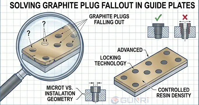
No. The plug pattern and density are determined at the manufacturing stage. The holes are drilled and the graphite is pressed in under high pressure. Retrofitting additional plugs into an existing plate would require drilling through the remaining bronze, which compromises the plate’s structural integrity.
What is the minimum wall thickness between graphite plugs?
The minimum bronze wall thickness between adjacent plugs should be 3 mm. Below this, the bronze web can crack under load, causing the plugs to loosen and fall out. The wall thickness is determined by the center-to-center spacing minus the plug diameter.
Do larger plugs always last longer than smaller plugs?
Yes, at the same coverage percentage, larger plugs provide more graphite volume per plug because the volume scales with the square of the diameter. An 8 mm plug at 30 percent coverage has four times the graphite volume of a 4 mm plug at the same coverage. However, the plug diameter is limited by the plate thickness.
How does graphite plug orientation affect performance?
The graphite plugs must be arranged so that the sliding direction crosses the plug rows perpendicularly. If the sliding direction is parallel to the plug rows, the graphite film will have un-lubricated stripes that cause localized galling and premature wear.
What happens if I use graphite with too low density?
Low-density graphite (below 1.60 g/cm³) is porous and wears quickly. It also produces more abrasive dust because the graphite particles break off more easily. The service life can be 40 to 60 percent shorter than with standard-density graphite. Always specify the graphite density in the purchase specification.