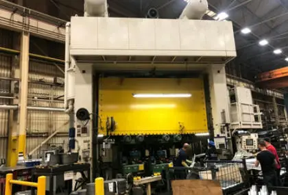
How to Design Maintenance-Free Guidance for 1000-Ton Automotive Transfer Presses
A few months ago, a production engineer from a Tier 1 automotive stamping supplier called me with a problem I hear more often than I should. Their 1000-ton transfer press — a machine that costs north of $2 million and runs three shifts — had been down for 18 hours. The root cause? The slide guidance system had worn past its adjustment limit. The oil lubrication lines were clogged again, the gib clearances had opened up, and the press couldn’t hold the ±0.05 mm parallelism required for the door inner panel they were running. The replacement parts alone ran $40,000. The lost production time was worse.
That call made one thing clear: if you are designing or specifying the guidance system for a large transfer press, “maintenance-free” is not a luxury. It is a direct driver of uptime, part quality, and total cost of ownership. Here is how to design it correctly from the start.
Step 1: Calculate the Loads Your Guidance System Must Handle
Before you select any component, you need to know the forces acting on the slide. A 1000-ton transfer press generates off-center loads that are significantly higher than a conventional straight-side press. The transfer mechanism — typically a three-axis servo-driven system — introduces dynamic side loads during part movement between stations.
The two critical values you need are maximum side thrust and PV (pressure × velocity) factor at the guidance interface. For a 1000-ton press running automotive body panels at 15–25 strokes per minute, side thrust at the gibs can reach 5–8% of the rated tonnage, or 50–80 tons of lateral force. Spread across four corner guide posts, each guide surface sees 12–20 tons of continuous side loading per stroke.
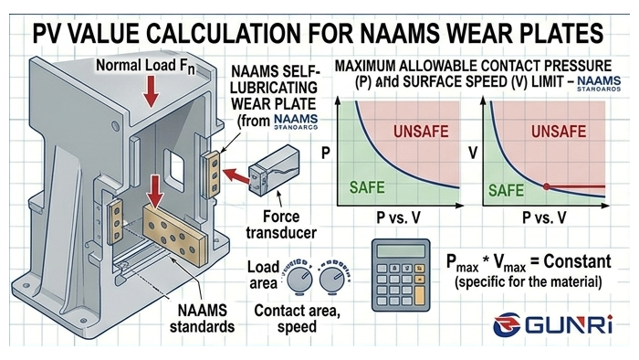
Calculate the PV factor using:
P = maximum contact pressure (MPa or psi) = side thrust ÷ projected bearing area
V = sliding velocity at the guidance surface (m/s or in/s)
PV = P × V
For graphite-plugged bronze wear plates, the safe continuous operating range is typically below 2.0 MPa·m/s. If your calculated PV exceeds this, you need to increase the bearing surface area or consider a hybrid system combining roller guides for the main slide and graphite bronze plates for the corner gibs.
Do not overlook how the press frame itself affects guidance loads. A 1000-ton transfer press with a full-eccentric gear drive and a box-type frame absorbs off-center forces much better than a conventional framed press. Less frame deflection under load means the guidance system sees significantly less diagonal side-loading. If you are specifying a new press, frame rigidity should be part of your guidance system discussion — not an afterthought.
Step 2: Choose the Right Guidance System Architecture
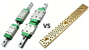
Based on the load calculations, the most reliable architecture for a 1000-ton automotive transfer press uses two complementary guidance mechanisms working together.
Eight-Point Roller Bearing Guides for the Main Slide
Eight-point roller guide systems use preloaded cylindrical or tapered cross-rollers running against hardened and ground steel guide rails mounted on the press uprights. They provide zero-clearance guidance with minimal friction — which means virtually no wear at the roller-rail interface under normal operation. These systems handle sliding speeds of 500–1000 mm/s, which covers the rapid traverse phase of a transfer press cycle. And because they come as permanently sealed, grease-packed cassettes, they eliminate the need for centralized oil lubrication in the main guide columns.
Include hydraulic overload protection (HOLP) in your specification. When a press is overloaded — for example, exceeding 1000 tons on a small forming area — the guidance rails and wear plates absorb the brunt of the shock. A fast-acting hydraulic overload system drops slide pressure instantaneously, preventing catastrophic damage to the guide rails and the graphite bronze wear plates. This is standard on most modern transfer presses, but it is worth confirming in your specification because the cost of a single overload event without HOLP can exceed the entire guidance system budget.
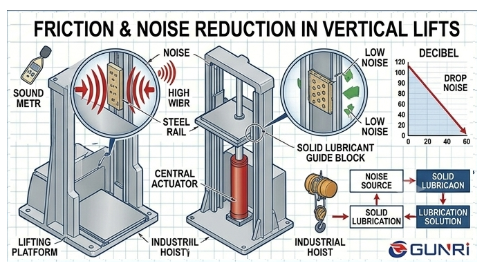
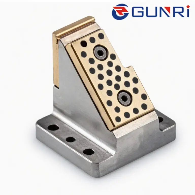
Self-Lubricating Graphite Bronze Wear Plates for the Gibs and Corner Slides
The corner gibs and secondary slide surfaces experience a different type of loading: high-impact, relatively slow-sliding contact with significant off-center forces. This is where graphite-plugged bronze wear plates outperform every other option. Here is why.
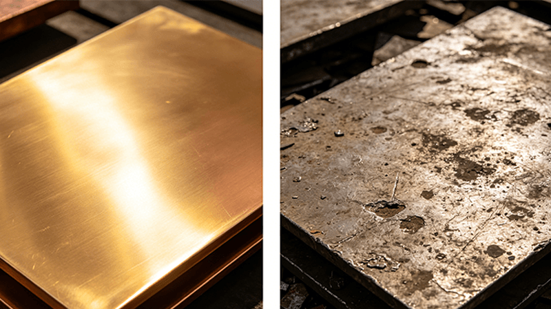
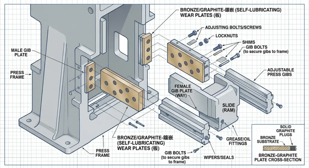
The aluminum-bronze alloy (typically CuAl10Fe5Ni5 or equivalent) provides a hard, wear-resistant surface that does not gall against hardened steel guide rails. The graphite plugs embedded in the bronze — arranged in a controlled geometric pattern — transfer a thin, consistent solid lubricant film onto the mating surface with every stroke. No oil. No grease. No lubrication lines. No filters. No pumps.
This matters in a 1000-ton transfer press because the die space must remain clean. Oil mist and grease purge from conventional lubrication systems can contaminate automotive stamping dies and sheet metal parts, causing rejection at the customer end. Graphite bronze plates eliminate that risk entirely while still maintaining the coefficient of friction around 0.06–0.12 that these interfaces need.
Specify wide connection spacing and eccentric pin adjustment. Transfer presses generate harsh asymmetrical forces because the transfer mechanism shifts part weight across stations. Wide connection spacing between the slide and the press ram distributes these off-center loads more evenly. Eccentric pin adjustments let you fine-tune the slide alignment during installation to compensate for any remaining asymmetry. This directly reduces the side load transmitted to the guidance system and extends wear plate life.
Step 3: Design the Gib Clearance with Thermal Expansion in Mind
A 1000-ton press running at production speed generates heat. The slide structure warms up, the guide rails warm up, and the wear plates warm up. If you design your gib clearance at cold assembly and do not account for thermal growth, you risk interference when the press reaches thermal steady state.
Steel has a coefficient of thermal expansion of approximately 12 × 10⁻⁶ /°C. For a guide rail that is 3 meters long, a 30°C temperature rise produces about 1.1 mm of total expansion. The slide structure expands differently from the uprights because of differences in mass and heat input. You must design the gib clearance to absorb this differential.
Our recommended starting clearance for graphite bronze wear plates on a 1000-ton transfer press is 0.08–0.12 mm per side at ambient temperature, depending on the guide rail length and expected thermal gradient. This provides enough room for thermal expansion while maintaining the precision alignment the tooling requires. If the press has water-cooled guide rails — which is becoming more common on modern transfer presses — you can tighten the cold clearance to 0.06–0.08 mm.
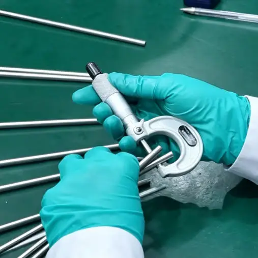
Step 4: Specify Flatness, Parallelism, and Surface Finish
In my experience, the most common reason guidance systems fail prematurely on large presses is not material selection — it is machining accuracy. A graphite bronze wear plate that is 2 meters long needs a flatness tolerance of 0.02 mm over its entire length, with a surface finish of Ra 0.8 μm or better on the sliding face. The mating steel guide rail must match or exceed these values.
For a 1000-ton press, the industry parallelism requirement between the left and right guide rails is typically within 0.03 mm over the full stroke length. Achieving this requires the mounting surfaces on the press uprights to be machined in a single setup on a large boring mill or gantry machine. Shim packs between the wear plates and the mounting surface are acceptable for final adjustment, but you should not rely on shims to correct a bad machining job.
Specify the graphite plug depth tolerance as ±0.3 mm relative to the bronze surface. Plugs that sit too high will transfer excessive graphite and create dust. Plugs that sit too low will not provide adequate lubrication film. The correct condition is a very slight protrusion of 0.1–0.2 mm, which wears flush during the first few hours of operation.
Step 5: Plan for Installation and Future Adjustment
No matter how well you design the system, the wear plates will eventually need replacement. A graphite bronze plate on a 1000-ton transfer press running 6000 hours per year typically lasts 2–3 years before the bronze thickness wears below the minimum structural requirement. The key is to make replacement predictable and fast.
Design the gib pockets with a consistent depth reference so replacement plates can be premachined and dropped in without field fitting. Include threaded jacking holes in the plate for easy removal. Use captive fasteners or threaded inserts so you do not lose hardware inside the press frame. Provide 1.0–1.5 mm of adjustable shim stock behind each plate for final parallelism tuning during installation.
We also recommend marking the initial gib clearance on the press frame with a permanent scribe line or a stamped reference tag. This gives the maintenance team a known baseline to measure against during periodic inspections. If the clearance increases by more than 0.05 mm from the as-installed value, it is time to inspect the wear plates and plan a replacement at the next scheduled shutdown rather than waiting for a failure.
Frequently Asked Questions
Q: Can I retrofit an existing 1000-ton press with graphite bronze wear plates if it currently uses oil-lubricated bronze?
A: In most cases, yes. The retrofit requires removing the existing oil-lubricated plates, verifying that the gib pocket dimensions match standard graphite bronze plate thicknesses, and installing the new plates with proper clearance. The oil lubrication system can remain in place but will no longer be needed, which saves on maintenance and consumables.
Q: How do graphite bronze wear plates perform under the snap-through loads common in blanking operations?
A: Snap-through or reverse-unloading creates a momentary loss of contact between the slide and the guidance surface. Graphite bronze plates handle this well because the solid lubricant is embedded in the material itself. Unlike an oil film that can be momentarily disrupted, the graphite is always present at the surface and begins lubricating again as soon as contact resumes.
Q: Do I still need roller guides if I use graphite bronze wear plates on all four corners?
A: For a press of this size, we recommend using both. Roller guides handle the high-speed traverse with zero clearance and minimal friction. Graphite bronze wear plates handle the high-impact, off-center loading at the corners where roller guides cannot fit. They are complementary, not alternatives.
Q: What is the typical cost difference between graphite bronze plates and oil-lubricated bronze plates for a 1000-ton press?
A: The material cost of graphite bronze plates is roughly 15–25% higher than equivalent oil-lubricated bronze plates. However, when you factor in the elimination of the oil circulation system — the pumps, filters, hoses, fittings, and the labor to maintain them — the total installed cost is typically lower for the graphite bronze solution. And the ongoing maintenance savings make the comparison even more favorable.