Graphite Plug Configuration Guide: How to Choose Plug Size, Pattern, and Density for Bronze Wear Plates
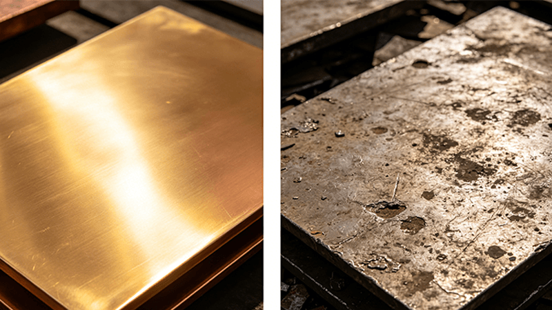
A few months ago, a mold shop reached out to me about a wear plate that had failed after only 8,000 cycles. The bronze itself looked fine — no cracks, no deformation. But the graphite plugs had completely worn down to nothing, and the mating surface was starting to gall.
After a quick look at their specs, the problem was obvious: the plugs were too small and too sparsely distributed for the load they were carrying. It wasn’t a material problem. It was a configuration problem.
I see this more often than I would expect. Engineers spend a lot of time picking the right bronze alloy — and that matters — but then leave the graphite plug configuration as an afterthought. The truth is, plug size, pattern, density, and depth are just as important as the base material. Get them wrong, and even the best C95400 plate will underperform.
This guide covers what you actually need to know about graphite plug configuration for bronze wear plates.
How Graphite Plugs Actually Work
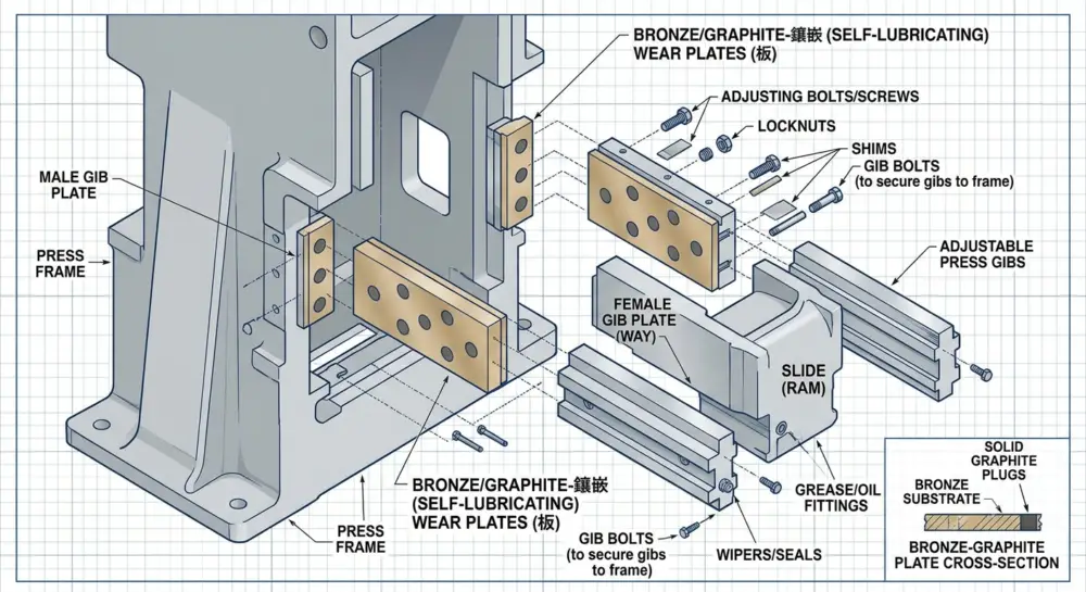
Graphite plugs in a bronze wear plate do one thing: they transfer a thin, dry film of lubricant onto the mating surface during sliding motion. This film reduces friction and prevents metal-to-metal contact between the plate and the opposing part.
Unlike oil or grease, graphite does not evaporate, degrade at high temperatures, or attract dust and debris. It is a solid lubricant with a coefficient of friction typically between 0.08 and 0.15 under dry conditions — and it can go as low as 0.01 with trace moisture present.
But here is the key: each plug only lubricates the area immediately around it. If your plugs are too far apart, you get dry zones where the bronze rubs directly against the mating surface. If they are too small, the film runs out before the next application cycle. And if they are too deep, you sacrifice structural integrity of the bronze matrix.
The Four Configuration Variables That Matter
A well-designed graphite plug configuration balances four variables:
- Plug diameter — typically 4 mm to 12 mm for wear plates
- Surface coverage (density) — what percentage of the plate surface is graphite
- Plug depth — how deep the graphite goes into the bronze
- Pattern and distribution — how the plugs are arranged on the plate
Each one depends on your specific operating conditions. Let me walk through them.
Plug Diameter: Matching Graphite Volume to Wear Rate
Standard graphite plug diameters for wear plates range from 4 mm to 12 mm. The right size depends mainly on two factors: the total sliding distance per cycle and the surface pressure.
4–6 mm plugs are common for light-duty applications like injection mold slide plates and FA automation guides. They work well when pressures stay below 10 MPa and sliding speeds are moderate.
8–10 mm plugs are the industry standard for most stamping die wear plates. They provide enough graphite volume to maintain a continuous lubricating film under pressures of 10–30 MPa.
10–12 mm plugs are used for heavy-duty applications — large stamping dies, mining equipment, and bridge bearings — where pressures exceed 30 MPa or sliding distances are long.
I generally recommend starting with 8 mm plugs for most general-purpose wear plates. It is a good balance between graphite volume and bronze land area. You can always adjust spacing to increase or decrease the total graphite coverage.
Surface Coverage: How Much Graphite Is Enough?
Surface coverage refers to the percentage of the plate sliding area occupied by graphite. This is the single most important configuration parameter.
Based on industry data from bearing manufacturers and bronze suppliers, the optimal coverage range for graphite plugs is 25% to 45% of the sliding surface area.
Here is a rough guide based on operating conditions:
- 15–25% coverage — Light-duty applications, low pressure, short stroke, intermittent motion. Common for automation guide plates and light injection molds. Risk: borderline lubrication under sustained use.
- 25–35% coverage — General-purpose stamping dies and molds. This is the sweet spot for most applications. Enough graphite for continuous film formation without compromising bronze strength.
- 35–45% coverage — Heavy loads, high temperatures, or long sliding distances. More graphite means more lubrication, but beyond 45% you start compromising the bronze matrix — it can lose compressive strength and the bronze land between plugs may deform under load.
For reference, a standard 3-row staggered pattern with 8 mm plugs at 12 mm pitch on a 100 mm wide plate gives roughly 30% coverage — right in the sweet spot.
Plug Depth: Dont Sacrifice Structural Integrity
Plug depth is often overlooked. The rule of thumb: plug depth should be 1 mm to 3 mm, and should generally not exceed 50–70% of the plate thickness.
Why? Because the graphite plug is not meant to be a deep reservoir. It transfers the film from the surface. Going deeper does not meaningfully increase lubrication life — it just weakens the bronze structure underneath.
For a typical 20 mm thick wear plate, 2.5 mm plug depth is standard. For thinner plates (e.g., 10 mm), keep it at 1.5 mm or less.
Pattern and Distribution: Why Staggered Rows Win
The arrangement of plugs on the plate surface determines how evenly the lubricating film is distributed.
Staggered rows (also called diamond pattern) are the most effective. Each row of plugs is offset by half the plug spacing, so the gaps in one row are covered by the plugs in the next row. As the mating surface slides across the plate, it never passes through a completely dry zone.
Straight grid patterns work too, but they create uninterrupted channels of bronze between plug rows. If the mating surface aligns with these channels, it can slide for a significant distance without contacting any graphite.
For most wear plates, a 3-row or 4-row staggered pattern with equal axial and lateral spacing is the standard recommendation. The spacing (pitch) between plugs usually ranges from 1.5 to 2.5 times the plug diameter.
How Load and Speed Affect the Configuration
The PV factor (Pressure x Velocity) is the fundamental design parameter for graphite plugged bearings and wear plates.
High load, low speed (typical for stamping dies and heavy press tools): The graphite film wears slowly but the pressure is high. Go with larger plugs (10 mm) and higher coverage (35–40%) to distribute the load. Staggered rows are essential here to avoid dry zones under sustained pressure.
Moderate load, moderate speed (injection mold slides, general automation): Standard 8 mm plugs at 30% coverage in a 3-row staggered pattern will handle most situations.
Low load, high speed (high-speed automation, packaging equipment): Smaller plugs (4–6 mm) with lower coverage (20–25%) work well. The faster motion helps distribute the graphite film more efficiently, so you do not need as much surface area.
Custom Configurations for Special Applications
Not every application fits neatly into standard patterns. Here are a few custom configurations I have seen work well in practice:
Edge-heavy patterns
For wear plates that experience higher edge loading — common in misaligned or cantilevered applications — concentrate more plugs along the loaded edge. A common approach is to use double rows along each edge with a single center row.
Mixed plug sizes
Some custom plates use alternating 6 mm and 10 mm plugs — the smaller plugs provide consistent light film coverage, while the larger ones act as graphite reservoirs for sustained operation. This is useful for reciprocating motion with long travel distances.
Anti-rotation patterns
For vertical slide plates where gravity could cause uneven plug wear, asymmetric patterns (tighter spacing at the bottom, wider at the top) can help compensate for differential loading.
Matching Configuration to Bronze Alloy
The bronze alloy you choose also influences what plug configuration is practical:
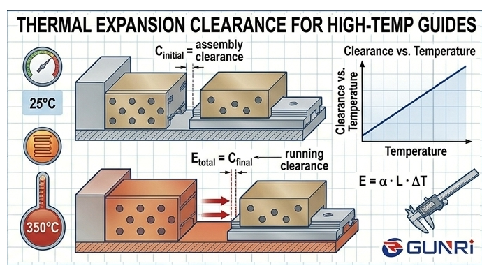
- C95400 aluminum bronze — Excellent plug retention due to its dense grain. Can handle tighter plug spacing (higher coverage) without risk of plug loosening. Best for high-temperature applications where thermal expansion might otherwise loosen plugs in softer alloys.
- C93200 bearing bronze — Easy to drill and plug. Standard patterns (3-row, 8 mm at 12 mm pitch) work well. This is the most forgiving alloy for plug configuration.
- C86300 manganese bronze — Requires careful drilling to avoid work-hardening. Plugs should be slightly smaller relative to hole diameter to account for the harder material. I recommend keeping coverage below 35% to maintain adequate bronze land for impact loads.
For a deeper comparison of these three alloys, see our graphite bronze wear plate alloy comparison guide.
Common Configuration Mistakes
After working with dozens of mold shops and equipment manufacturers, here are the most frequent mistakes I see:
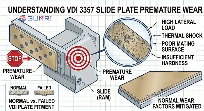
- Plugs too small for the load — Using 4 mm plugs on a heavy stamping die that needs 10 mm. The graphite wears out in days.
- Too much coverage — Pushing above 50% graphite surface area. The bronze loses structural integrity and the plate deforms under load.
- Shallow plugs on thick plates — Plug depth of 0.5 mm on a 25 mm plate. The graphite film is too thin to last.
- No staggered pattern — Straight grid rows create dry channels. Switch to staggered.
- Ignoring edge loading — Uniform spacing on a plate that carries more load at one edge. Concentrate plugs where the load is.
Putting It All Together
Here is a practical starting point for most general-purpose graphite bronze wear plates:
- Plug diameter: 8 mm
- Coverage: 30% of sliding surface area
- Depth: 2.5 mm (for 20 mm plate thickness)
- Pattern: 3-row staggered, 12 mm pitch
- Alloy: C93200 SAE 660 unless conditions demand otherwise
Adjust from there based on your actual load, speed, temperature, and mounting conditions. If you are unsure, start conservative — it is easier to add plugs than to remove them.
If you need a custom configuration for your specific die or machine, browse our full range of graphite bronze wear plates — we can manufacture plates with any plug size, pattern, and density you specify.