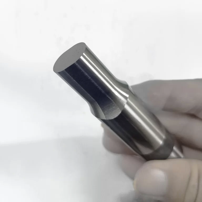
Why Ejector Sleeves Fail in Die Casting: Six Failure Modes and How to Read Them
A failed ejector sleeve is not a random event. In a die casting die it almost always falls into one of six patterns, and each pattern points at a specific cause — clearance, surface, steel, or installation. The useful skill is not preventing all failures, it is reading which one you have so you fix the cause instead of replacing the part and waiting for it to happen again.
This article works through the six modes, with the measurement you need to confirm each one.
1. Bore galling and pin seizure
What you see. The bore is scored, material is transferred between pin and sleeve, and eventually the pin seizes or the sleeve rotates in its seat.
What it means. Running clearance went to zero at operating temperature — usually because the sleeve was bored to a room-temperature clearance that closed up once the die heat-soaked, or because the bore finish was too rough to hold an oil film.
How to confirm. Measure the pin OD and sleeve ID cold, then calculate both at die temperature using the expansion of each material. If the calculated clearance is below roughly a micron, galling is expected rather than surprising.
Fix. Open the ID band, polish the bore, and confirm the surface is actually nitrided rather than merely heat treated. Check that the pin itself is not oversized or bent — a bent pin will gall any sleeve.
2. Aluminum build-up on the outside diameter
What you see. A grey film of aluminum on the sleeve OD that grows shot by shot, eventually interfering with the counterbore and marking the casting.
What it means. Adhesion, not wear. Molten aluminum wets steel; a nitrided, polished surface resists it, a ground-only surface does not, and a case that has worn through cannot resist at all.
How to confirm. Check case depth on a sectioned sample. If the case is gone at the point of build-up, the sleeve was not the problem — the run length was.
Fix. Restore nitriding, specify a polished OD as well as a polished bore, and review whether the sleeve sits in a hot spot where a coating would pay for itself.
3. Longitudinal cracking
What you see. A crack running along the sleeve axis, usually starting at a corner or at a change in section, sometimes only visible after the sleeve is removed.
What it means. Thermal fatigue. The sleeve expands against a cooler pin every cycle; over enough cycles the surface initiates a crack and it propagates. This is the characteristic failure of die casting ejection tooling and the reason hot-work steel is specified.
How to confirm. Look at the crack origin — thermal fatigue cracks start at the surface, often in a network of fine cracks before one opens up. A crack starting at an internal corner with no surface crazing points instead at a stress concentration or a machining defect.
Fix. Verify core hardness is in the 38–42 HRC band (too hard a core is brittle, too soft and it deforms), check that the case is not disproportionately thick for the section, and remove sharp internal corners in the design.
4. Flash ring on the casting
What you see. A thin fin of metal at the base of the boss, growing over production.
What it means. The clearance between sleeve ID and pin has opened — from wear, from an ID that was oversized at manufacture, or from the sleeve having been run past its wear limit.
How to confirm. Measure the bore at three heights and two axes. A bore that is oval indicates side load; a bore that is uniformly larger indicates wear or a manufacturing error.
Fix. Establish a wear limit and measure against it on a schedule rather than waiting for flash to appear. Flash is the symptom that arrives after the tolerance is already gone.
5. Sheared or deformed head
What you see. The head has separated from the body, or the shoulder is mushroomed.
What it means. Ejection load exceeded what the wall section can carry, or the sleeve is not properly seated so the load is applied off-axis. A sleeve retained by friction rather than by a shoulder seat will almost always end this way.
How to confirm. Check the seating face in the ejector plate for contact pattern. Partial contact — a ring on one side only — confirms misalignment rather than overload.
Fix. Machine a proper shoulder seat, increase wall thickness if the ejection load is genuinely high, and check ejector plate parallelism.
6. Pin bending inside the sleeve
What you see. The pin bows, the sleeve bore wears on one side, ejection becomes uneven.
What it means. The sleeve is not supporting the pin over the full stroke. A short sleeve guides the pin only at its base, leaving the free length to buckle under load.
How to confirm. Compare sleeve length with ejection stroke. If the sleeve covers less than the stroke, the unsupported length is the buckling length.
Fix. Lengthen the sleeve to cover the stroke, or reduce the pin’s free length with a stepped design.
The measurement routine that catches all six
Rather than inspecting when something breaks, measure four things at commissioning and then at fixed intervals:
| Measurement | Tool | What it catches |
| Sleeve ID at 3 heights, 2 axes | Bore gauge | Wear, ovality, manufacturing error |
| Pin OD at contact band | Micrometer | Pin wear, bending |
| Coaxiality of sleeve to seat | CMM or indicator | Installation error |
| Case depth on a sample | Microhardness traverse | Nitriding that did not take |
The first set of readings is the baseline that makes every later reading meaningful. Without it, a bore that measures 0.02 mm over nominal tells you nothing — it may have been made that way.
What we specify, and why
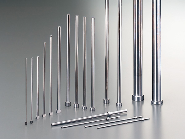
For die casting duty we produce ejector sleeves in SKD61 (AISI H13 equivalent) at 38–42 HRC core hardness with a nitrided case above HV900, ground and then polished in the bore, up to 1,000 mm long, to 0.01 mm precision and 0.06 mm coaxiality. For abrasive-filled plastic molds we produce SKH51 at 59–61 HRC to 0.005 mm precision and 0.01 mm coaxiality.
Those two specifications exist because the failure modes above split cleanly along that line: thermal fatigue dominates in die casting, abrasive wear dominates in filled resin.
Die casting ejector sleeve specification and clearance method
All ejector sleeve grades and sizes
FAQ
How long should an ejector sleeve last in a die casting die?
There is no universal number — it depends on alloy, cycle time, die temperature, clearance and whether the sleeve sits in a hot spot. What matters is establishing a wear trend from a baseline measurement so replacement happens before flash appears.
Can a failed sleeve be repaired?
Galling and minor wear can sometimes be corrected by re-polishing and re-nitriding if there is material to remove. Cracking and sheared heads cannot — replace those.
Does a coating help?
It can, for adhesion-dominant failures where the sleeve sits in a hot spot. It is not a substitute for correct clearance; a coated sleeve with the wrong clearance still galls.
Should I change grade after a failure?
Only if the failure mode points that way. Changing grade without identifying the mode usually just changes the failure, not the interval.
Send us the failed part and the die conditions
We will identify the mode and propose a specification change, rather than quoting the same sleeve again.