Ball Cages for Bore Gage and Electronic Bore Probe Heads
You push a bore gage into a 12 mm hole in a hardened steel bushing. The two contact fingers spring out against the wall. As you rock the gage to find the diameter, the reading wanders — not because the hole is out of round, but because the internal plunger that pushes the fingers is binding in its guide. You take three readings, get three numbers, and pick one. That is the symptom of a gage head whose plunger guidance has degraded.
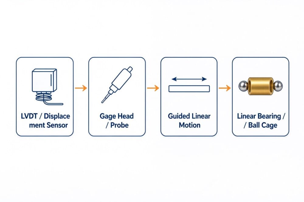
Inside an electronic bore probe, the contact fingers act on a small plunger that slides axially. That plunger is what drives the LVDT or half-bridge sensor that outputs the diameter. If the plunger sticks or cocks, the sensor reads the plunger position — which is no longer the true bore size. The mechanical guide on that plunger is part of the measurement path, even though the guide itself is not a sensing element.
The Plunger Guide Inside a Bore Probe
A bore probe is a slender tube. The measuring head at the bottom carries the contact fingers, the actuating plunger, and the transducer. The plunger has to slide freely in the head as the fingers move in and out, but it cannot tilt — a tilted plunger changes the finger geometry and biases the diameter reading.
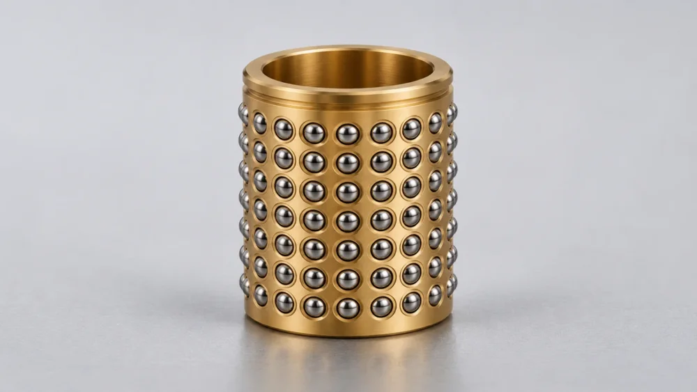
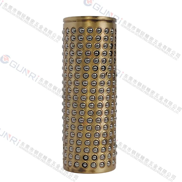
A miniature ball cage sleeves the plunger inside the head body. Rows of balls run on the plunger shaft, keeping it concentric while allowing axial travel. Because the stroke is short (the fingers move fractions of a millimeter per measurement), the balls shuttle in slotted windows rather than recirculate. The cage occupies very little radial space, which matters because the head tube itself is sized to fit inside the bore being measured.
Why Friction in the Plunger Path Matters
Bore gages are comparative instruments. You set the master ring, then measure the part. Any friction in the plunger path shows up as a difference between the up-stroke and down-stroke readings — hysteresis. The gage reads differently when you approach the diameter from the plus side versus the minus side.
A plain plastic or sintered bushing has sliding friction. Breakaway force is real, and it is not constant over millions of measurements as the bushing wears. A ball cage converts that to rolling contact. The plunger moves with consistent, low resistance, and the up-stroke and down-stroke readings converge.
The cage does not make the gage more accurate. It removes the plunger guide as a source of error in the existing measurement chain.
The Envelope Gets Tight on Small Bores
Measuring a 5 mm bore means the gage head tube has to fit inside that 5 mm. Everything inside — fingers, plunger, transducer, guide — has to pack into a diameter smaller than the part being checked. There is no room for a standard linear bearing.
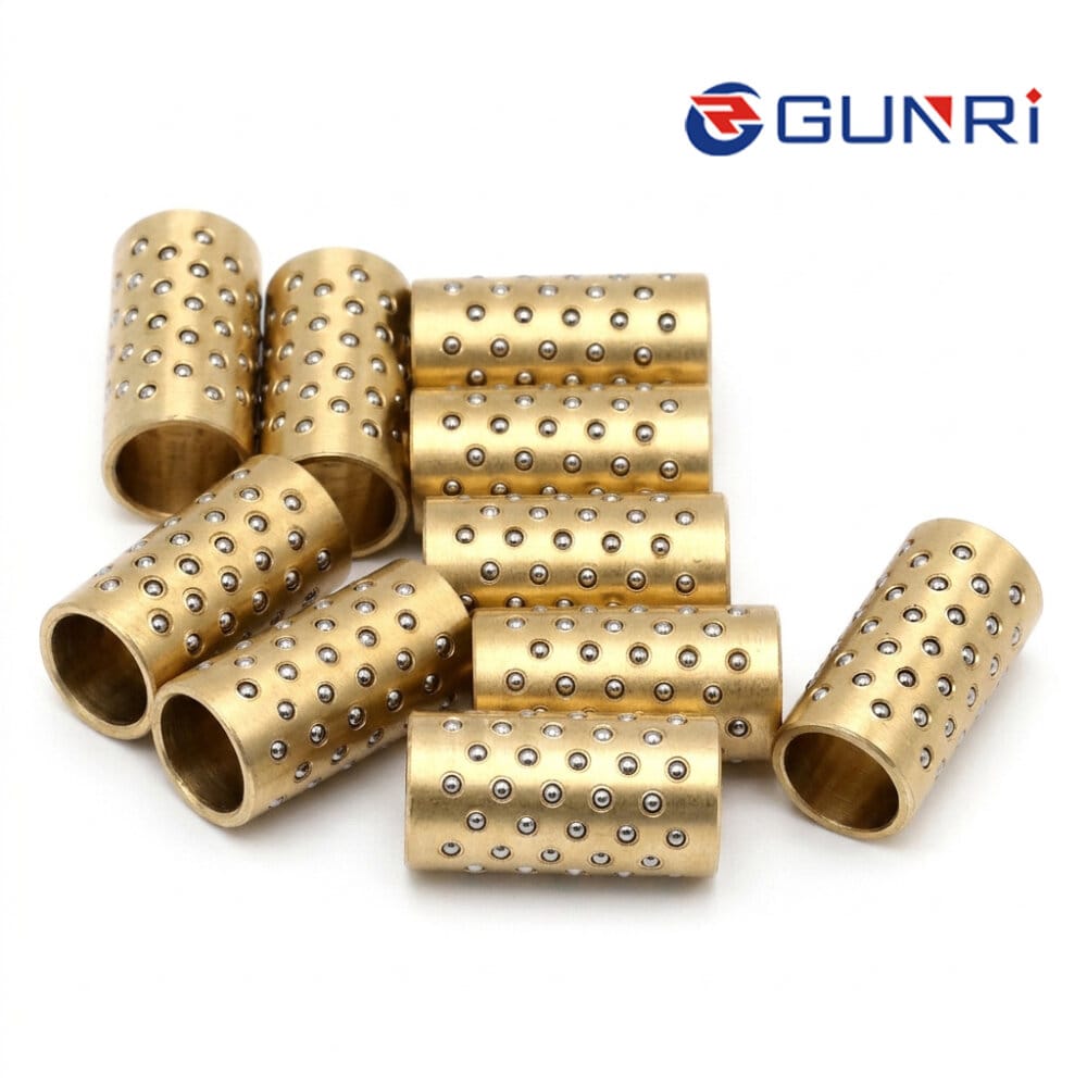
We build these cages down to a 2.0 mm inner diameter, with 0.6 mm balls and a cage length as short as 8 mm. That is small enough to sleeve a plunger inside a head tube that itself fits a miniature bore. On larger bore probes (50 mm and up), the cage scales up; OD can run to 400 mm on the large end, though bore-probe cages rarely exceed 15 to 20 mm OD.
Material for a Gage Head
A bore probe lives in a metalworking environment. Coolant mist, chips, and hand oil are present. The cage material has to survive that without swelling or seizing.
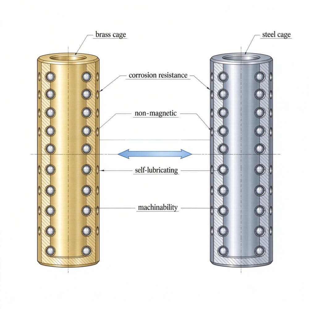
- Brass or bronze is the default. Easy to machine, dimensionally stable, and takes optional graphite solid-lubricant plugs when the probe is sealed and cannot be relubricated in the field.
- Aluminum alloy is used when the probe is long and the moving mass at the end matters for operator feel.
- POM resin is chosen for low-cost handheld bore gages where the probe is disposable or repaired rather than rebuilt, and where dry running is acceptable.
Oil grooves can be cut into the cage bore when a light grease film is specified, and slotted windows can be elongated to reduce edge loading on the balls during the short stroke.
The Cage Is Not the Sensor
Worth stating plainly: the ball cage centers the plunger. It does not measure displacement. The LVDT, the half-bridge, or the digital indicator is the sensor. When you are designing a gage head, the cage is a mechanical component in the same category as the plunger shaft and the return spring. For background on how the two relate, see ball cages for LVDT gage heads and cages for displacement sensors, where the same plunger-guidance logic applies.
Because gage heads are rebuilt and recalibrated on schedule, ball cage failure modes and life is a useful read before you commit to a material. The most common field issue is not ball wear — it is contamination getting into the windows, which is why sealed heads and graphite-plug or POM options matter.
Specifying the Cage
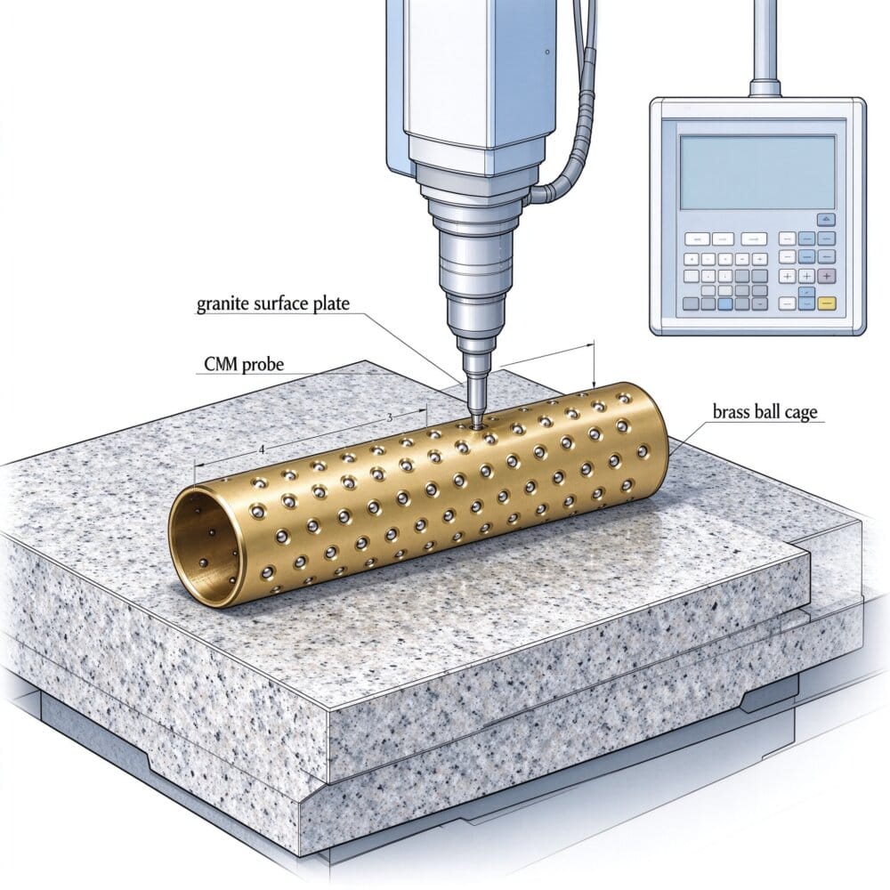
We work from your drawing. Send the plunger shaft diameter, the available bore in the head tube, the stroke, and the environment (coolant, hand oil, dry). Tolerances, ball grade, and preload are specified to your drawing and application requirements. First articles are CMM-inspected and the report ships with the parts. We accept STEP, IGES, and SLDPRT files, and there is no minimum order quantity — a one-off replacement for a legacy bore head runs the same workflow as production.
Send your drawing or a sample to our engineering team for a no-obligation review. We accept STEP, IGES, and SLDPRT files. Every cage is CMM-inspected before shipment.