Ball Cages for CMM Touch-Probe Heads
A touch-trigger probe sits on the end of a CMM ram. The ruby ball on the stylus taps the part, the stylus deflects by a few micrometers, and a switch inside the head latches the machine position. The repeatability of that trigger point is what the whole CMM measurement budget is built on.
Inside the head, the stylus stem does not float freely. It sits in a guided seat, preloaded by a spring, and returns to a repeatable center after each trigger. If that seat has sliding friction or stick-slip, the trigger point shifts with approach direction and the CMM starts reporting part features that are not really there. The question for the probe designer is how to guide the stylus stem — or the internal actuator plunger that carries the stylus — so it centers without hysteresis.
Where a Ball Cage Fits in a Probe Head
A touch-trigger head is a precision mechanism, and not every head uses ball cages. Many rely on kinematic mounts, spring-loaded plungers, or flexures. But when the internal design calls for a short-stroke, axial or limited-tilt guide on a plunger that carries the stylus collet, a miniature ball cage is one of the options on the table.
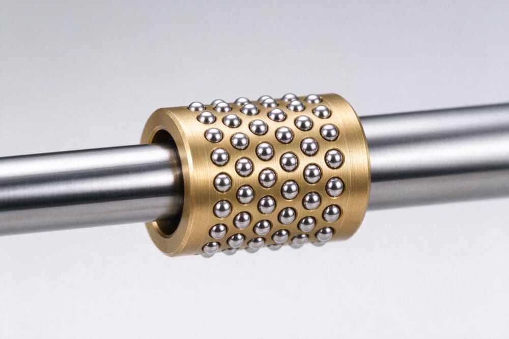
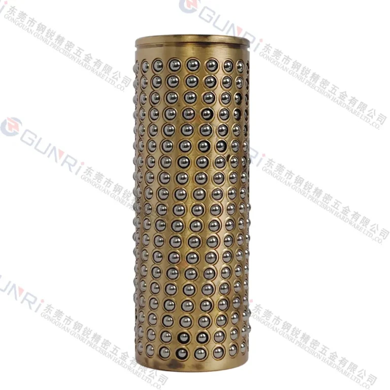
The cage sleeves the plunger that holds the stylus shank. Rows of balls run on the plunger’s ground shank, carrying the small side load from the stylus overhang and letting the plunger move with rolling contact. The stroke is tiny — fractions of a millimeter to a few millimeters — so the balls shuttle in slotted windows rather than recirculating. The preload spring does the centering; the cage does the straightness.
Why Rolling Contact Matters in a Trigger Mechanism
On a plain bushing, the plunger sticks before it slides. That static friction threshold means the stylus must deflect by a small but uncertain amount before the plunger even begins to move inside its seat. On a CMM, that uncertainty lands directly in the measurement error budget.
A ball cage lowers the breakaway force. The balls roll rather than slide, so the plunger responds to the smallest stylus deflection and the trigger happens at a more consistent contact force across approach directions. The cage does not improve the switch itself — it just removes the plunger seat as a source of hysteresis.
Miniature Envelope for a Probe Head
Probe heads are small. The stylus shank is 2 to 6 mm in diameter on most shop-floor heads, and the head body around it has to leave room for the trigger switch, the cable, and the collet. There is no space for a linear bearing cartridge.
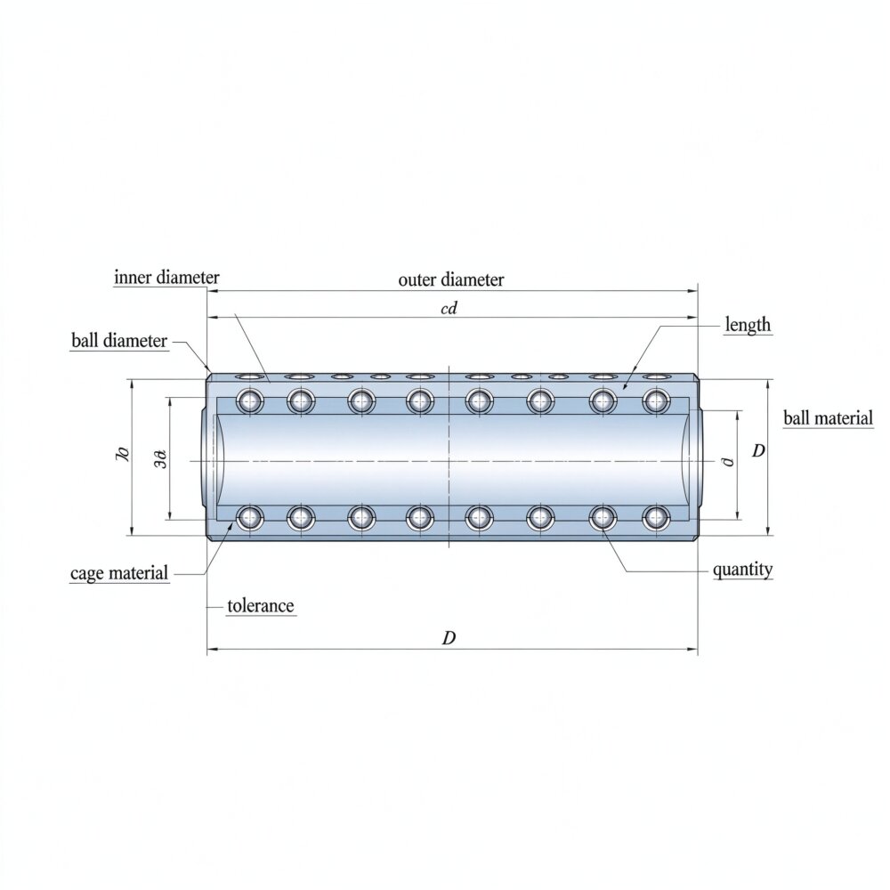
We build these cages down to a 2.0 mm inner diameter, with 0.6 mm balls and cage lengths as short as 8 mm. That is small enough to nest inside a probe body without increasing its diameter. The balls are staked into the cage windows so they cannot fall out during the repeated trigger cycles and during probe disassembly for stylus changes.
Material and Lubrication Inside a Head
Inside a probe head, lubrication choices are constrained. Oil can attract dust and cause drag. Grease packs onto the ball surfaces and changes breakaway force as it ages. The cleanest options are:
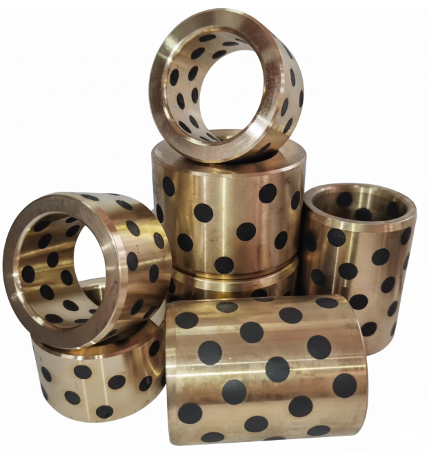
- Bronze cage with graphite solid-lubricant plugs. The graphite transfers a dry film to the ball and shaft. No oil to dry out or attract grit.
- POM resin cage. Self-lubricating, no lubricant at all. Chosen when the head is sealed and maintenance-free, and when the load is very light.
- Brass or aluminum cage with a light oil groove. Used when a small amount of controlled lubrication is acceptable and the head is rebuilt on a schedule.
Aluminum also cuts moving mass on fast-approaching probes, which matters for dynamic probing where the stylus approaches the part quickly. Brass is the default when stiffness and long-term dimensional stability matter more than mass.
Inspection That Matches the Application
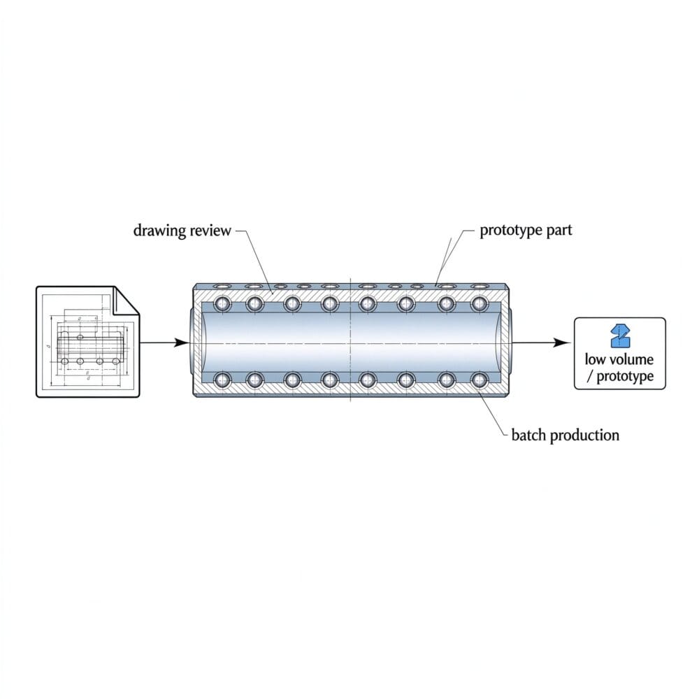
A probe-head cage is a small, precision part. First articles are CMM-inspected for bore, OD, window spacing, and ball protrusion. The inspection report ships with the batch so the probe manufacturer can confirm the cage meets its drawing before it goes into a head. We accept STEP, IGES, and SLDPRT files. Tolerances, ball grade, and material hardness are specified to your drawing and application requirements.
For the broader metrology and semiconductor inspection world, the same cage geometry shows up on semiconductor metrology stages, where short-stroke guidance and low hysteresis are also the design drivers. If you are wondering how tightly a cage should be fitted, the clearance vs preload note walks through the tradeoff. And because every first article is measured, the CMM inspection report practice is part of the normal workflow, not an add-on.
When a Cage Is Not the Answer
A ball cage is a mechanical guide. It is not a bearing, not a switch, and not a stylus. Some probe designs use flexures instead of any sliding or rolling element at all, and that is the right choice when tilt is the motion you need and axial translation is unwanted. A cage is the option when the plunger genuinely slides axially and needs to do it without friction hysteresis.
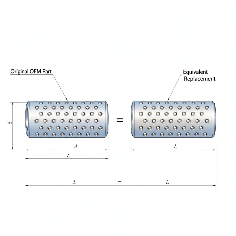
There is no minimum order quantity, so a prototype cage for a new probe design ships on the same terms as a 10,000-piece production run. We also build interchange equivalents for common off-the-shelf cage lines when you need a drop-in replacement.
Not sure whether a cage or a bushing is right for your application? Send us the stroke, load, and available envelope, and we will tell you honestly which one makes more sense — even if it is not us.